This document outlines the procedures for installing and removing Small Form-Factor Pluggable (SFP) modules and various Field Replaceable Units (FRUs) in Cisco 1100 Terminal Gateway Routers. It covers the installation and removal of SFP modules, Network Interface Modules (NIMs), Solid State Drive (SSD) storage, and the setup of LTE dongle support.
Function Description
The Cisco 1100 Terminal Gateway Routers are designed to provide robust network connectivity, supporting a range of modules for enhanced functionality. The core function of these routers is to facilitate terminal services and network routing.
Small Form-Factor Pluggable (SFP) Modules: These modules are designed to provide optical Gigabit Ethernet connectivity. They are optional components that can be installed to extend the router's capabilities for fiber optic network connections. The use of SFP modules allows for flexible deployment in various network environments where optical transmission is required, offering high-speed data transfer over longer distances compared to traditional copper cabling.
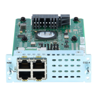
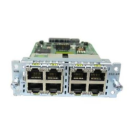
Network Interface Modules (NIMs): NIMs are crucial for expanding the router's interface capabilities. The document specifically mentions several NIMs: NIM-ES2-4, NIM-ES2-8, NIM-16A, NIM-24A, C-NIM-2T, and NIM-VAB-A. These modules likely provide additional Ethernet ports, serial interfaces, or other specialized network connections, allowing the router to connect to a wider array of devices and networks. For instance, NIM-ES2-4 and NIM-ES2-8 suggest Ethernet switch modules with 4 and 8 ports, respectively, while NIM-16A and NIM-24A could indicate modules with a higher density of specific interface types. C-NIM-2T is noted to be supported on specific SKU of the Cisco 1100 Terminal Services Gateway, indicating specialized or high-performance network connectivity. NIM-VAB-A is also supported on the Cisco 1100 Terminal Services Gateway, suggesting another variant of network interface. These modules are essential for tailoring the router to specific network requirements, such as connecting multiple local area networks (LANs) or integrating with legacy systems.
Solid State Drive (SSD) Storage: The M.2 storage module provides internal storage capabilities for the router. This SSD storage is crucial for storing operating system images, configuration files, logs, and potentially other data required for the router's operation. The use of SSDs ensures faster boot times and improved overall system performance compared to traditional hard disk drives, contributing to the router's reliability and responsiveness.
LTE Dongle Support: This feature enables the router to utilize a USB LTE dongle for cellular network connectivity. This is particularly useful for providing primary or backup internet access in locations where wired connections are unavailable or unreliable. The LTE dongle allows the router to connect to mobile broadband networks, offering flexibility and mobility in network deployment. This function ensures continuous network operation, which is critical for business continuity and remote site connectivity.
Usage Features
The document provides clear, step-by-step instructions for installing and removing various components, highlighting ease of use and maintenance.
SFP Module Installation:
- Simplicity: The process for installing SFP modules is implied to be straightforward, allowing users to easily add optical connectivity.
- Flexibility: The optional nature of SFP modules means users can customize their router's connectivity based on their specific needs, without being forced to purchase unnecessary interfaces.
NIM Installation and Removal:
- Modular Design: The ability to install and remove NIMs signifies a modular design, allowing for easy upgrades, replacements, and customization of the router's interfaces.
- Clear Steps: The instructions for NIM installation involve locating the slot, loosening screws, inserting the module, and tightening screws, indicating a user-friendly process.
- Graceful Shutdown: The emphasis on gracefully shutting down a running NIM before removal is a critical operational feature, preventing data corruption or damage to the module. This highlights the importance of proper procedure for maintaining system integrity.
SSD Storage Installation and Removal:
- Standardized Component: The M.2 storage module is a common form factor, suggesting that replacement or upgrade components are readily available.
- Accessibility: The SSD panel is located on the bottom side of the chassis, indicating a design that allows for relatively easy access for maintenance or upgrades.
- Clear Procedure: The steps involve unfastening screws, plugging in the new module, securing it, and reinstalling the panel, making the process manageable for users.
LTE Dongle Support:
- Micro-SIM Card Integration: The process involves inserting a micro-SIM card into the USB LTE dongle, which is a standard procedure for cellular devices.
- Dust Cover Protection: The use of a dust cover for the micro-SIM slot indicates attention to detail in protecting the delicate SIM card and slot from environmental factors.
- Antenna Orientation: The note about adjusting antenna orientation for optimal performance is a practical usage tip, ensuring users can maximize cellular signal strength and data rates.
- Mounting Procedure: The detailed steps for connecting the USB LTE dongle to the terminal server, including using R-Brackets and wall-mounting brackets, demonstrate a comprehensive approach to secure and stable deployment. The recommended torque for screws ensures proper installation and durability.
Maintenance Features
The document places a strong emphasis on safety and proper procedures, which are key aspects of device maintenance.
Safety Warnings:
- Electrical Storms: Warnings against servicing equipment with outdoor connections during electrical storms are crucial for user safety, preventing electric shock from lightning.
- Hazardous Voltages: The warning about hazardous network voltages in interface ports, even when the unit is off, underscores the need to disconnect cables before servicing. This is vital for preventing electric shock during maintenance.
- Coaxial Cable Shielding: The requirement for the coaxial cable shield to be connected to the building earth is a critical safety measure, reducing the risk of electric shock.
- Antenna Installation: The directive to refer to national and local codes for proper antenna installation and grounding highlights the importance of compliance with safety standards.
- Blank Faceplates and Covers: The warning about the importance of blank faceplates and cover panels for electric shock prevention, fire safety, EMI containment, and cooling airflow is a significant maintenance feature. It ensures that the system operates safely and efficiently, and that internal components are protected. Operating the system without these covers can lead to safety hazards and system malfunctions.
Preventative Measures:
- Graceful Shutdown: The repeated warning about gracefully shutting down NIMs before removal is a preventative maintenance measure, safeguarding against damage to the NIM card. This practice extends the lifespan of the components and maintains system stability.
- No User Replaceable Parts (Main Chassis): The explicit warning "Do not remove the main cover of the chassis as there are no user replaceable parts inside" and "No serviceable parts inside. To avoid risk of electric shock, do not open" is a critical maintenance instruction. It guides users on which parts are user-serviceable (like SFP modules, NIMs, SSDs, and LTE dongles) and which are not, preventing unauthorized tampering that could lead to damage or void warranties. This also protects users from potential electric shock from internal components.
- EMI Containment: The role of blank faceplates and covers in containing electromagnetic interference (EMI) is a maintenance feature that ensures the router does not disrupt other equipment and operates within regulatory limits.
- Cooling Airflow: The function of blank faceplates and covers in directing cooling airflow is essential for maintaining optimal operating temperatures within the chassis, preventing overheating and extending the life of internal components.
Compliance:
- IEC 60825-1 Ed. 3 and 21 CFR 1040.10 and 1040.11: The statement regarding pluggable optical modules complying with these standards indicates adherence to international and national safety regulations for laser products. This ensures that the modules are safe to handle and operate under specified conditions.
Overall, the document provides a comprehensive guide for the installation, usage, and maintenance of various modules within the Cisco 1100 Terminal Gateway Routers, emphasizing safety, modularity, and ease of serviceability for user-replaceable components.