1-14
Cisco ONS 15454 Procedure Guide, Release 8.5.1
78-18537-01
Chapter 1 Install the Shelf and Backplane Cable
NTP- A119 Install the Alarm Expansion Panel
Note The AIC-I card provides direct alarm contacts (external alarm inputs and external control outputs). In
the ANSI shelf, these AIC-I alarm contacts are routed through the backplane to wire-wrap pins
accessible from the back of the shelf. When you install an AEP, the direct AIC-I alarm contacts cannot
be used. Only the AEP alarm contacts can be used.
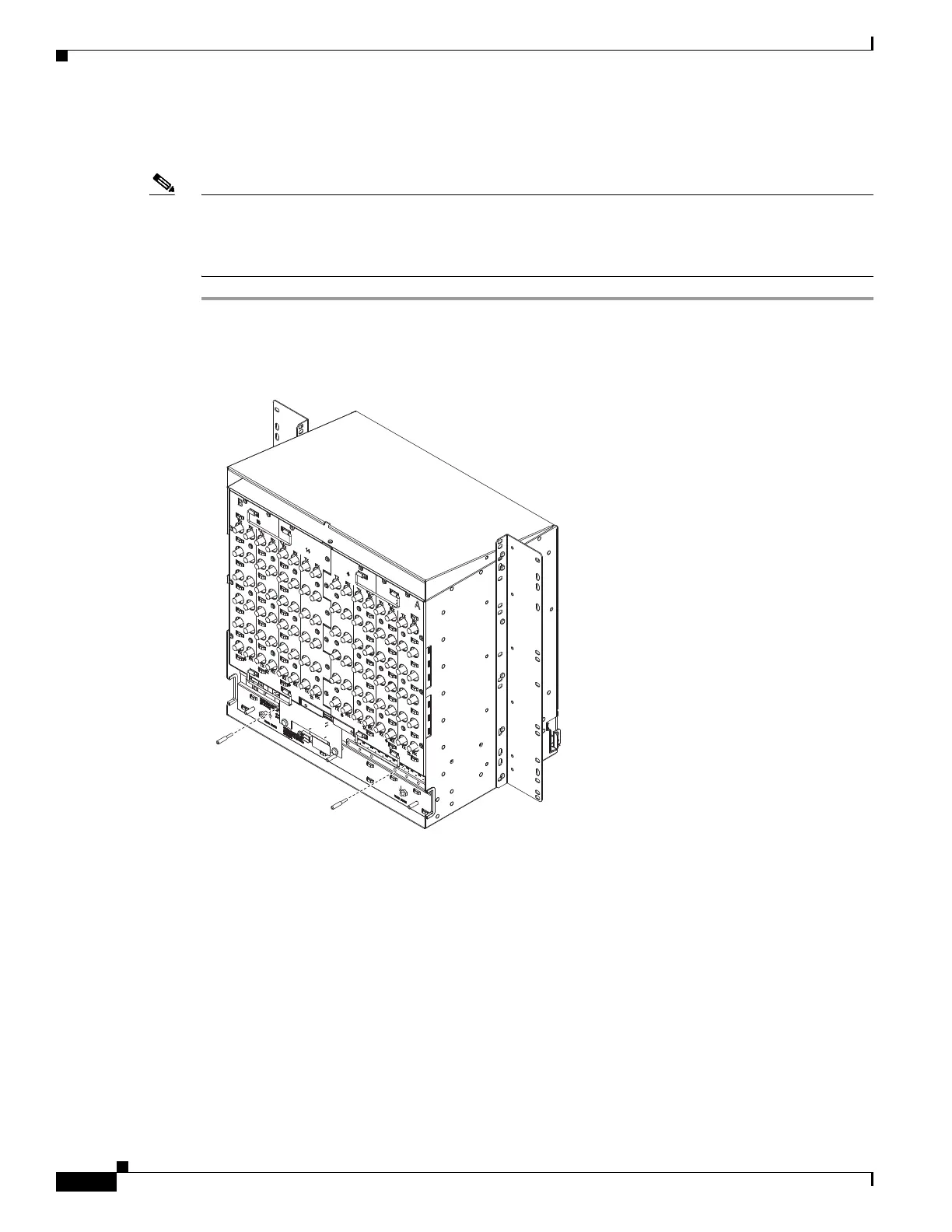
Step 1 Remove the two backplane screws. Replace the two screws with standoffs. Insert the longer standoff on
the left and the shorter standoff on the right (Figure 1-2).
Figure 1-2 Replace Backplane Screws with Standoffs
Step 2
Attach the remaining two standoffs on either side of the backplane (Figure 1-3).
Step 3 Position the AEP board over the standoffs.
Onsite/Remote Onsite
Security Level None

 Loading...


