4-11
Cisco PIX Security Appliance Hardware Installation Guide
78-15170-03
Chapter 4 PIX 515/515E
Installing Failover
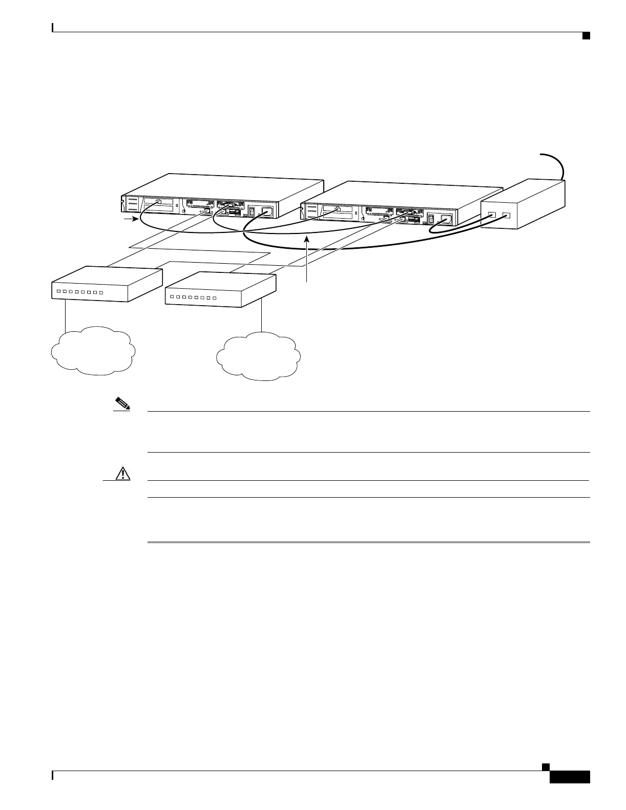
Figure 4-11 shows an example of a minimally configured PIX 515/515E with only the two interfaces on
the motherboard used for network traffic.
Figure 4-11 Failover Connections
Note All enabled interfaces must be connected between the active and standby units. Only configure the active
unit. On the PIX 515/515E, the active unit is indicated by the ACT LED on the front panel. (See
Figure 4-3.)
Caution Do not turn the power on until the units are connected and the primary unit is configured completely.
Step 7 Use the power switch at the back of the units to power on the primary unit and then power on the standby
unit.
Within a few seconds, the active unit automatically downloads its configuration to the standby unit.
If the primary unit fails, the secondary unit automatically becomes active.
Inside
network
Internet
D
O
N
O
T
I
N
S
T
A
L
L
I
N
T
E
R
F
A
C
E
C
A
R
D
S
W
I
T
H
P
O
W
E
R
A
P
P
L
I
E
D
C
O
N
S
O
L
E
1
0
/
1
0
0
E
T
H
E
R
N
E
T
0
L
in
k
F
D
X
F
D
X
1
0
0
M
b
p
s
L
in
k
1
0
0
M
b
p
s
F
A
I
L
O
V
E
R
1
0
/
1
0
0
E
T
H
E
R
N
E
T
1
PIX-515
D
O
N
O
T
I
N
S
T
A
L
L
I
N
T
E
R
F
A
C
E
C
A
R
D
S
W
I
T
H
P
O
W
E
R
A
P
P
L
I
E
D
C
O
N
S
O
L
E
1
0
/
1
0
0
E
T
H
E
R
N
E
T
0
L
i
n
k
F
D
X
F
D
X
1
0
0
M
b
p
s
L
in
k
1
0
0
M
b
p
s
F
A
IL
O
V
E
R
1
0
/
1
0
0
E
T
H
E
R
N
E
T
1
PIX-515
27883
PIX 515
Primary unit
Stateful Failover
dedicated interface
cable
Failover
serial cable
PIX 515
Standby unit
UPS
(not supplied)
Power
Inside switch
Outside switch

 Loading...


