2-5
Cisco Video Surveillance PTZ IP Camera Installation Guide
OL-28954-01
Chapter 2 Installing the Camera
Installing the PTZ IP Camera
Step 5 Push the seal (B) into the housing (D).
Step 6 Insert the seals (C) into unused holes on the seal (B) to avoid moisture.
Step 7 Secure the sealing nut (E) and hex nut from the bottom of the camera tightly.
Connecting the Cables
Perform the following steps to install and connect the I/O wires and RJ45 Ethernet cable.
Caution Avoid touching the circuit boards to prevent damage by electrostatic discharge.
Note We recommend using 24AWG (0.51 mm) gauge cable.
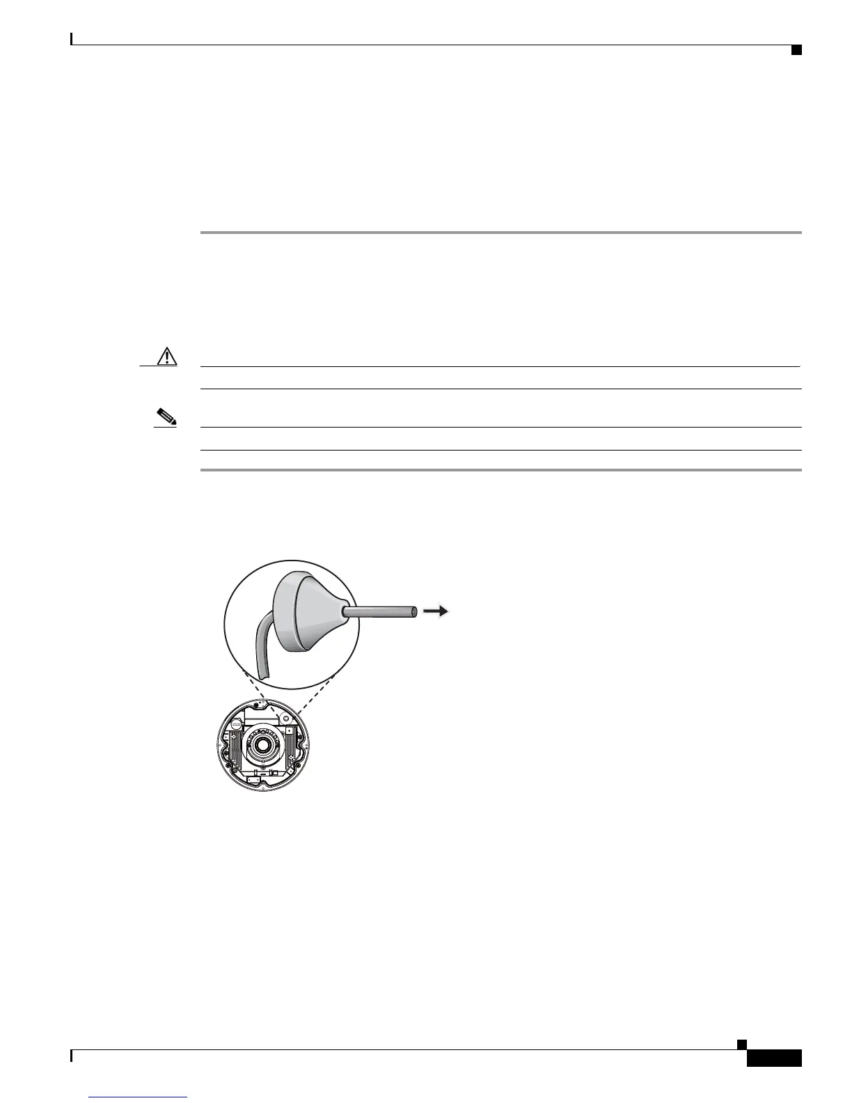
Step 1 Use a small-size flat-blade screwdriver to secure I/O wires to the included terminal blocks.
Step 2 Drill a hole on the rubber seal plug and insert an Ethernet cable (without a connector) through the
opening.
Step 3 Strip about 1/2 inch (12 mm) of the sheath from the Ethernet cable.
Step 4 Use an RJ45 crimping tool to attach the Ethernet wires to a connector. When done, connect the cable to
the camera’s Ethernet RJ45 socket.