Quick Start Guide
Cisco Small Business
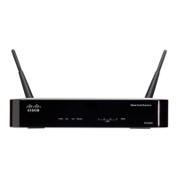
Model RVS4000
4-Port Gigabit Security Router with VPN
Package Contents
• RVS4000 Router
•Network Cable
• Power Adapter
•Stands
•Quick Start Guide
• Software and Documentation on CD-ROM
Product Overview
Thank you for choosing the Cisco RVS4000 4-Port Gigabit Security Router with
VPN. The RVS4000 Router is an advanced Internet-sharing network solution for
your small business needs. Like any router, it lets multiple computers in your
office share an Internet connection.
This router also features a built-in 4-port full-duplex 10/100/1000 Ethernet
switch to connect four PCs directly, or you can connect more hubs and switches
to create as big a network as you need.
The Virtual Private Network (VPN) capability creates encrypted “tunnels”
through the Internet, allowing users to securely connect into your office
network from offsite.
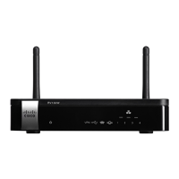
Front Panel
The LEDs are on the front panel of the router.
POWER LED—Lights up green to indicate the router is powered on. The LED
flashes when the router is running a diagnostic test.
DIAG LED—If this light is off, the system is ready. The Diag LED blinks red during
firmware upgrades.
IPS LED—The IPS LED lights up when the Intrusion Prevention System (IPS)
function is enabled. If the LED is off, then IPS functions are disabled. The IPS LED
flashes green when an external attack is detected. It flashes red when an
internal attack is detected.
ETHERNET Port LEDs (1-4)—For each LAN port, there are three LEDs. If a port
LED is continuously lit green, the router is connected to a device at the speed
indicated through the corresponding port (1, 2, 3, or 4). The LED flashes green
when a router is actively sending or receiving data on that port.
INTERNET LED—The Internet LED lights up green to indicate the line speed of
the device attached to the Internet port. If the router is connected to a cable or
DSL modem, typically the 100 LED will be the only LED lit up, indicating
100 Mbps. Flashing indicates activity.
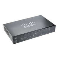
Back Panel
The Ethernet ports, Internet port, Reset button, and Power port are on the back
panel of the router.
RESET Button—The Reset button can be used in two ways:
• If the router is having problems connecting to the Internet, press the Reset
button for just a second with a paper clip or a pencil tip. This is similar to
pressing the reset button on your PC to reboot it.
• If you are experiencing extreme problems with the router and have tried all
other troubleshooting measures, press and hold in the Reset button for
10 seconds. This will restore the factory defaults and clear all of the router
settings, such as port forwarding or a new password.
INTERNET Port—Provides a WAN connection to a cable modem or DSL
modem.
ETHERNET Ports (1-4)—Provide a LAN connection to network devices, such
as PCs, print servers, or additional switches.
POWER Port—Connects the router to power via the supplied AC power
adapter.
Placement Options
You can place the router horizontally on the rubber feet, mount it in the stand, or
mount it on the wall.
Desktop Option
For desktop placement, place the Cisco RVS4000 router horizontally on a
surface so it sits on its four rubber feet.
Stand Option
To install the router vertically in the supplied stands, follow the steps below.
To place the router vertically, follow these steps.
STEP 1 Locate the left side panel of the router.
S
TEP 2 With the two large prongs of one of the stands facing outward, insert
the short prongs into the little slots in the router and push the stand
upward until the stand snaps into place.
274946
POWER DIAG IPS ETHERNET
RVS4000
10
100
1000
1 2 3 4
INTERNET
STEP 3 Repeat step 2 with the other stand.
Wall Option
To mount the Cisco RVS4000 router on the wall, follow these steps.
STEP 1 Determine where you want to mount the router and install two
screws (not supplied) that are 2-9/16 in. apart (approximately
64.5 mm).
S
TEP 2 With the back panel pointing up (if installing vertically), line up the
router so that the wall-mount crisscross slots on the bottom of the
access point line up with the two screws.
S
TEP 3 Place the wall-mount slots over the screws and slide the router down
until the screws fit snugly into the wall-mount slots.
193817
Wall
mount
slots
2-9/16