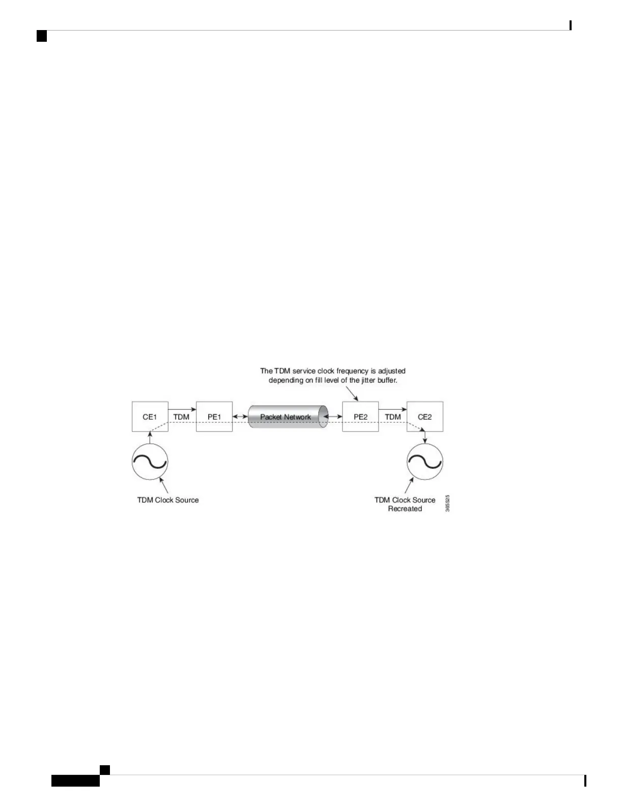
clock, and the receiving IWF creates a clock based on packet arrival. The service clock frequency is adjusted
depending on fill level of the jitter buffer.
• When sending TDM digital signal over PSN, the TDM data is inserted into packets in the master IWF
and sent to the desired destination (slave IWF).
• The rate at which the packets are transmitted to the PSN is constant. Due to the nature of the PSN, the
packets might arrive to the destination in bursts and with varying rate.
• The long-term average of this rate is equal to the insertion rate at the master IWF. Moreover, the packets
in the PSN might switch their order and even be lost.
• The IWF at the far end of the PSN (slave IWF) recovers the service clock (E1/T1) used by the master
IWF.
• The recovered clock is used by the slave IWF for the transmission of the data back into the TDM lines.
• The master IWF aggregates the TDM data and creates the PWE packets; these packets are transmitted
to the PSN.
• The packets are received by the slave IWF and stored in a jitter buffer designed to absorb the packet
delay variation (PDV).
• The packets are extracted from the jitter buffer and the clock recovery algorithm updates the service
clock based on the timing information available.
Differential Clock Recovery in CESoPSN
DCR (Differential Clock Recovery) is another technique used for Circuit Emulation (CEM) to recover clocks
based on the difference between PE clocks. The clock from the TDM domain is mapped through the packet
domain. It differs from ACR in that a PRC traceable clock is used at each end. Differential timing messages
are used to tune the TDM clock frequency from the sending end to the receiving end. Both ends have a source
traceable reference. Because of this, the recovered clock is not affected by PDV when using DCR.
In contrast with DCR, a PRC traceable clock source is available at each end. ACR is used when a traceable
source is not available at both ends of the PSN link.
The recreated service clock accuracy is dependent on the accuracy between the sending and receiving PRC
frequencies.
48-Port T1/E1 CEM Interface Module Configuration Guide, Cisco IOS XE Fuji 16.7.x (Cisco NCS 4200 Series)
40
Clock Recovery System for CESoPSN
Differential Clock Recovery in CESoPSN