Cisco Unified Communications 500 Series Model UC 540 Quick Start Guide 11
S
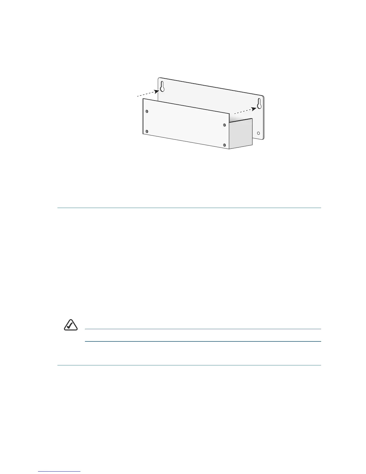
TEP 3 Attach the power supply bracket to the wall.
The following illustration shows the wall-mount bracket for the
power supply and the mounting-screw holes on the back of the
bracket.
a. Attach the bracket to the wall by using the mounting hardware
specified in Step 1.
b. Orient the front and back of the power supply vertically.
c. Position the end nearest the power cable at the top.
Grounding the Chassis
The UC 540 chassis must be reliably grounded with a supplementary
ground wire to comply with the relevant product safety standards. This
supplementary ground is in addition to the ground connection made by the
power cord.
For the supplementary ground connection, use size 14 AWG (2 mm) or
larger copper wire and an appropriate user-supplied ring terminal with an
inner diameter of 1/4 inch (5 to 7 mm).
NOTE The UC 540 is not NEBS-compliant.
To connect the chassis to a reliable earth ground:
STEP 1 Strip one end of the ground wire to the length required for the
ground lug or terminal.
• For the ground lug, strip approximately 0.75 in. (20 mm).
• For the user-provided ring terminal, as required.
 Loading...