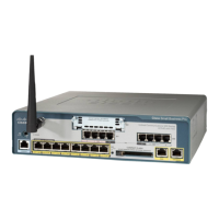
Cisco Unified Communications 500 Series Model UC 540 Quick Start Guide 13
Connecting the Equipment
STEP 1 Insert the power cord into the back of the UC 540. Do not connect
to power.
STEP 2 Screw the antenna onto the threaded connector on the front panel.
Orient the antenna to point upward.
STEP 3 Connect the interfaces and devices as described below.
1. If a T1/EI controller is installed in the VIC slot, connect either a T1/E1 straight-through cable
(identical to the Ethernet straight-through cable), or a T1/E1 crossover cable to the controller.
Connect the other end of the cable to the ISDN provider equipment. The cable that you use
depends on the type of termination on the network interface device (NID), and is the point in
which the telephone company network ends and connects with the wiring at the customer
site.
Type of Connection Description
DSL, cable modem, or
broadband network devices.
Connect the supplied Ethernet cable from the
device to the WAN port on the front panel of the
UC 540. Cisco strongly recommends using
Category 5 or better cable.
PSTN analog trunks Connect an RJ-11 cable to one of the Line (FXO)
ports on the front panel of the UC 540. Connect the
other end of the cable to a PSTN line or a station
interface on a PBX.
ISDN line
1
(only applies to model
UC540W-BRI-K9)
Connect the cable provided by the ISDN provider to
one of the Line (BRI) ports on the front panel of the
UC 540. Connect the other end of the cable to the
ISDN provider equipment.
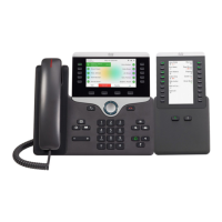
IP phones and other network
devices (such as a wireless
access point, IP video
cameras, and network
attached storage (NAS)
devices)
Connect an Ethernet network cable from the
network device to one of the PoE ports on the UC
540 front panel.
Fax machine or analog phone Connect an RJ-11 cable to one of the Phone (FXS)
ports on the front panel of the UC 540. Connect the
other end of the cable to the fax machine or phone.
ESW switch Connect an Ethernet network cable from the
expansion port of the UC 540 to one of the uplink
ports on the switch.
 Loading...