3-20
Cisco UCS C220 M4 Server Installation and Service Guide
OL-32473-01
Chapter 3 Maintaining the Server
Installing or Replacing Server Components
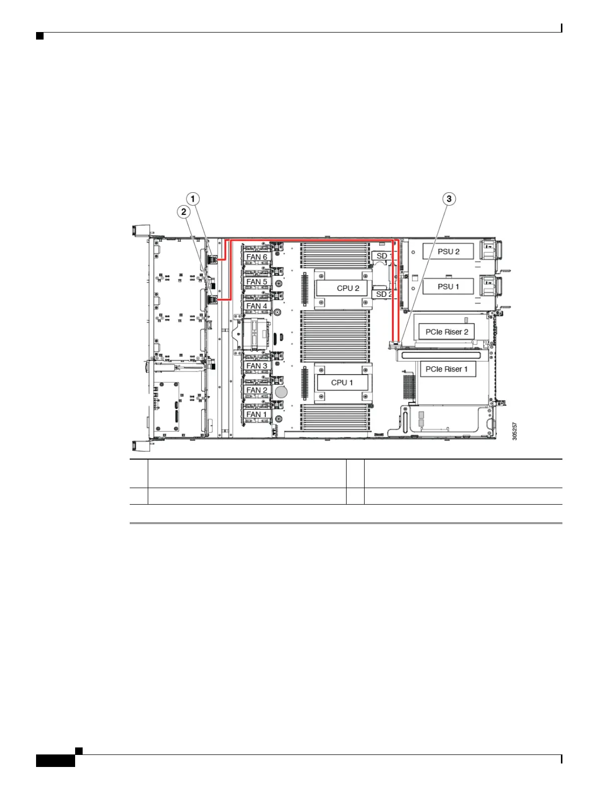
c. Connect the two ends of the cable to the PCIe connectors on the drive backplane.
Connect the cable labeled Port A to the Port A connector; connect the cable labeled Port B to the
Port B connector (see Figure 3-10).
Step 4 Replace the top cover.
Step 5 Replace the server in the rack, replace cables, and then power on the server by pressing the Power button.
Figure 3-10 PCIe Riser Version 2B Cabling to Drive Backplane
1 PCIe connector, Port A 3 Cable connector on PCIe riser 2B
(UCSC-PCI-2B-220M4)
2 PCIe connector, Port B

 Loading...


