3-41
Cisco UCS C220 M4 Server Installation and Service Guide
OL-32473-01
Chapter 3 Maintaining the Server
Installing or Replacing Server Components
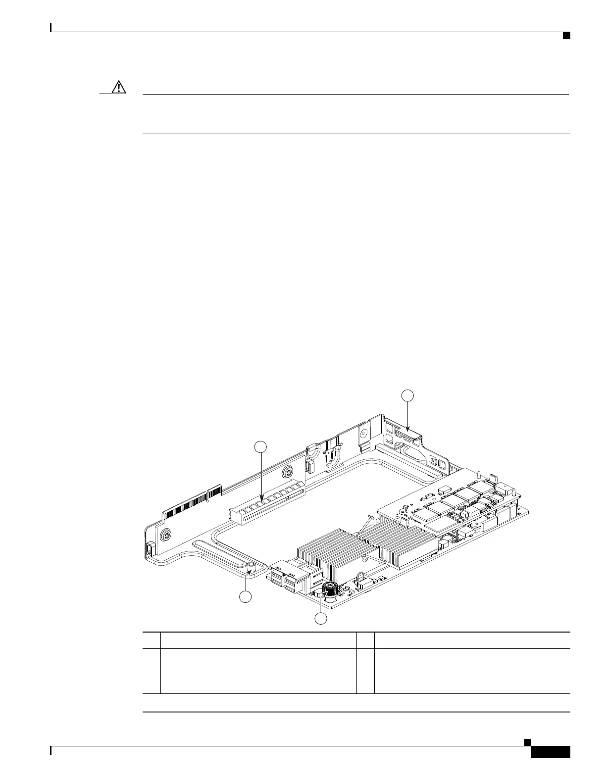
Caution Be careful when inserting the card to the riser so that you do not scrape electronic components on the
underside of the card on features of the riser. The threaded standoff on the riser that is for the thumbscrew
on the card might snag and damage the card components (see item 4 in Figure 3-21).
a. With the riser upside down, set the card on the riser. Align the right end of the card with the
alignment channel on the riser; align the connector on the card edge with the socket on the riser (see
Figure 3-21).
b. Being careful to avoid scraping the underside of the card on the threaded standoff on the riser, push
on both corners of the card to seat its connector in the riser socket.
c. Tighten the single thumbscrew that secures the card to the riser bracket.
Step 5 Return the riser to the server:
a. Align the connector on the riser with the socket on the motherboard. At the same time, align the two
slots on the back side of the bracket with the two pegs on the inner chassis wall.
b. Push down gently to engage the riser connector with the motherboard socket. The metal riser bracket
must also engage the two pegs that secure it to the chassis wall.
Step 6 Reconnect the SAS cable to its connector on the RAID controller card.
Step 7 Replace the top cover.
Step 8 Replace the server in the rack, replace cables, and then power on the server by pressing the Power button.
Figure 3-21 Cisco Modular RAID Controller Card in Riser
1 Card socket on upside down riser 3 Thumbscrew on card
2 Guide channel on riser 4 Threaded standoff on riser
CAUTION: Do not scrape the underside of
the card on this threaded standoff.

 Loading...


