Cisco UCS C480 M5 Memory Guide
Server CPU Module Bay Layout
3
Server CPU Module Bay Layout
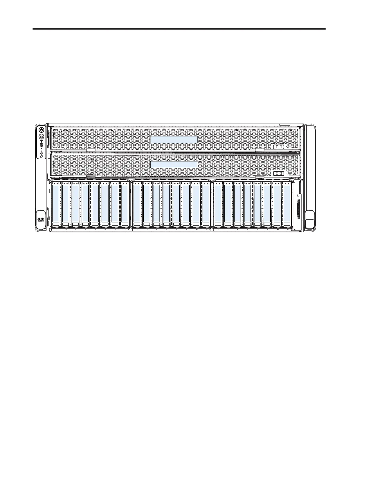
The front of the C480 M5 server is shown in Figure 1. Notice that there are two CPU Module bays, the lower
bay (Bay 1) and the upper bay (Bay 2).
The CPU numbering is as follows:
■ Lower Bay: CPU1 and CPU2
■ Upper Bay: CPU3 and CPU4
Figure 1 C480 CPU Module Bays
Drive Bay 01
Drive Bay 02
Drive Bay 03
Drive Bay 04
Drive Bay 05
Drive Bay 06
Drive Bay 07
Drive Bay 08
Drive Bay 09
Drive Bay 10
Drive Bay 11
Drive Bay 12
Drive Bay 13
Drive Bay 14
Drive Bay 15
Drive Bay 16
Drive Bay 17
Drive Bay 18
Drive Bay 19
Drive Bay 20
Drive Bay 21
Drive Bay 22
Drive Bay 23
Drive Bay 24
306011
CPU Module Bay 1
CPU Module Bay 2
Each CPU has six memory channels, and each channel controls two memory DIMMs.
The channel numbering for each CPU is as follows:
Lower Bay:
■ CPU1: A, B, C, D, E, F
■ CPU2: G, H, J, K, L, M
Upper Bay:
■ CPU3: A, B, C, D, E, F
■ CPU4: G, H, J, K, L, M

 Loading...