Implementing Multicast Routing on Cisco IOS XR Software Cisco ASR 9000 Series Routers
Information About Implementing Multicast Routing
MCC-18
Multicast Configuration Guide
OL-
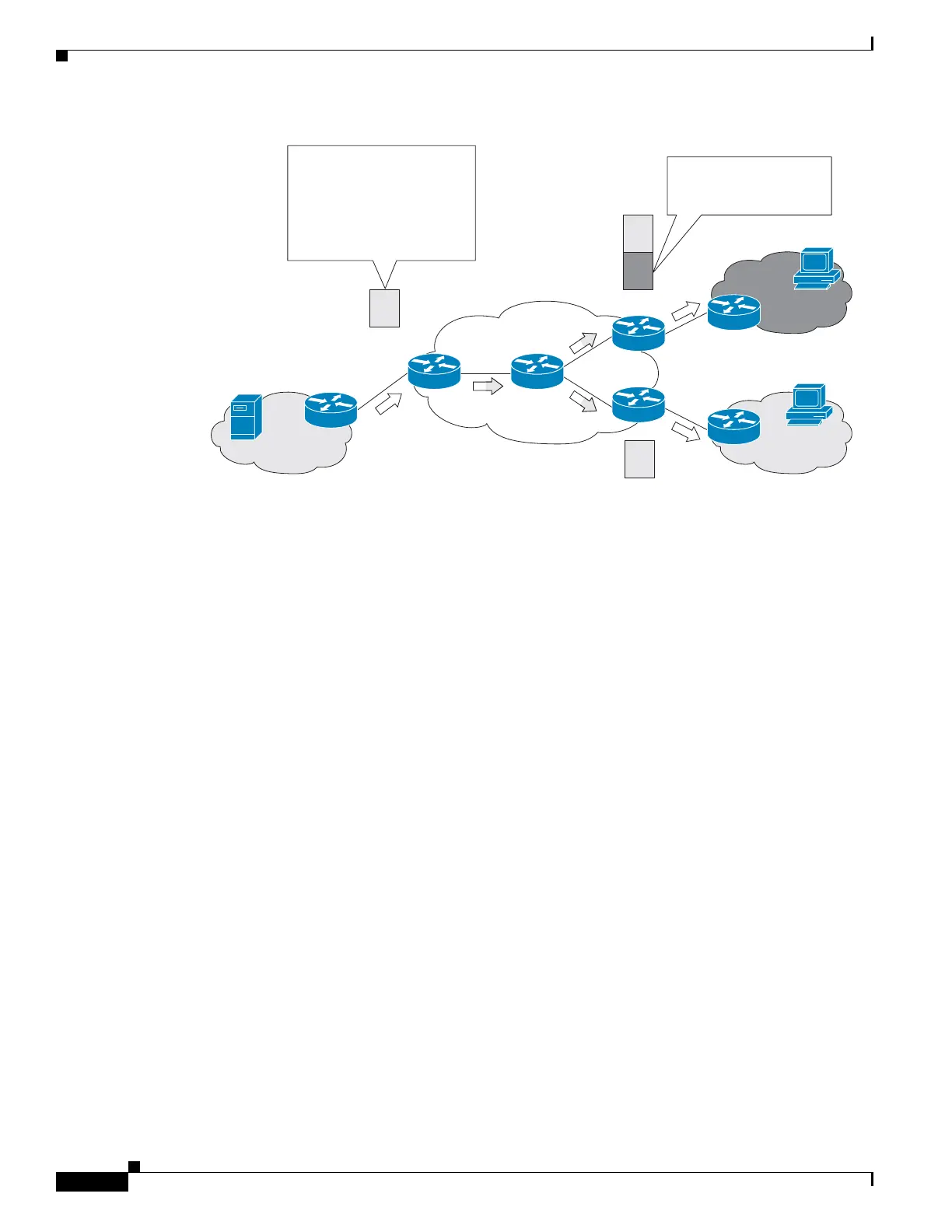
Figure 7 Source MVRF at the Receiver PE Router
Receiver MVRF on the Source PE Router
To provide extranet MVPN services to enterprise VPN customers by configuring the receiver MVRF on
the source PE router, complete the following procedure:
• For each extranet site, you would configure an additional MVRF on the source PE router, which has
the same default MDT group as the receiver MVRF, if the MVRF is not already configured on the
source PE.
• In the receiver MVRF configuration, you would configure the same unicast routing policy on the
source and receiver PE routers to import routes from the source MVRF to the receiver MVRF.
If the originating MVRF of the RPF next-hop is remote (receiver MVRF on the source PE router), the
the join state of receiver VRFs propagates over the core through the MDT of each receiver.
Figure 8 illustrates the flow of multicast traffic in an extranet MVPN topology where a receiver MVRF
is configured on the source PE router. An MVRF is configured for VPN-A and VPN-B on PE1, the
source PE router. A multicast source behind PE1 is sending out a multicast stream to the MVRF for
VPN-A, and there are interested receivers behind PE2 and PE3, the receiver PE routers for VPN-B and
VPN-A, respectively. After PE1 receives the packets from the source in the MVRF for VPN-A, it
independently replicates and encapsulates the packets in the MVRF for VPN-A and VPN-B and forwards
the packets. After receiving the packets from this source, PE2 and PE3 decapsulate and forward the
packets to the respective MVRFs.
VPN-A
VPN-A
VPN-B
Source
Receiver
Receiver
281306
PE1
CE
CE
CE
P
PE3
PE2
MVRF for VPN-A
MVRF for VPN-A
MVRF for VPN-A
MVRF for VPN-B
Packets are received and
replicated in the MVRF for
VPN-A on PE1
In addition, the packets are
replicated to PE2 and PE3 as
both are connected to
receivers in VPN-A
Packets are decapsulated
and replicated in the MVRF
for VPN-B on PE2
 Loading...