172.110UK User Manual
Introduction
Thank you for choosing a Citronic D1000 power amplifier as part of your sound reinforcement system. Our new class-D
circuit design provides an efficient amplifier within a compact and lightweight form factor. Please read this manual fully
and follow the instructions to achieve the best results from your amplifier and to avoid damage through misuse.
Warning
To prevent the risk of fire or electric shock, do not expose any of the components to rain or moisture.
If liquids are spilled on the casing, stop using immediately, allow unit to dry out and have checked by qualified personnel
before further use. Avoid impact, extreme pressure or heavy vibration to the case.
No user serviceable parts inside – Do not open the case – refer all servicing to qualified service personnel.
Safety
• Check for correct mains voltage and condition of IEC lead before connecting to power outlet.
• Ensure speaker leads are good condition with no shorted connections or damaged plugs.
• Check that the impedances of speaker loads do not exceed the minimum stated load for the amplifier.
• Do not allow any foreign objects to enter the case or through the ventilation grilles.
Placement
• Keep out of direct sunlight and away from heat sources.
• Keep away from damp or dusty environments.
• When rack-mounting, ensure adequate support for the base of the amplifier and firm fixings for the front.
• Ensure adequate airflow and do not cover cooling vents at the front and rear of the amplifier.
• Ensure adequate access to controls and connections.
Cleaning
• Use a soft cloth with a neutral detergent to clean the casing as required.
• Use a vacuum cleaner to clear ventilation grilles of any dust or debris build-ups.
• Do not use strong solvents for cleaning the unit.
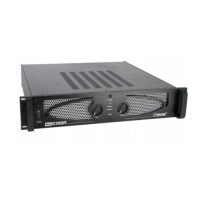
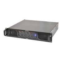
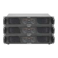
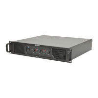
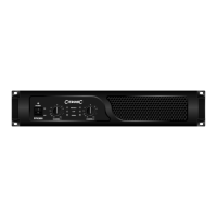
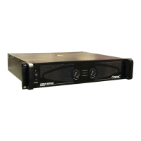
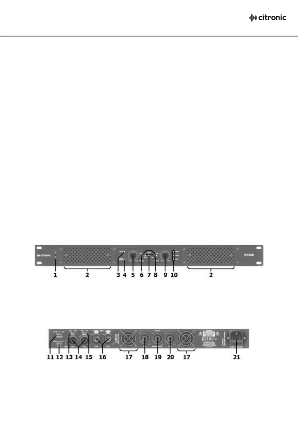
Front Panel
Cooling vents – do not cover or obstruct
CH.B output level control
CH.A output level control
Amplifier operating mode LEDs
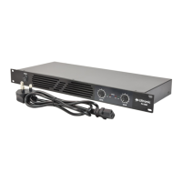
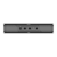
Rear Panel
Input SENSITIVITY switch 0.775V / 1.00V / 1.44V
Cooling fan vents – do not cover or obstruct
Amplifier MODE switch – Bridge / Stereo / Parallel
CH.B output - SPK connector
75Hz LOW CUT filter on/off switch
BRIDGE mono output - SPK connector
CH.A+B signal link output (XLR balanced/unbalanced)
CH.A output - SPK connector
IEC mains power inlet & fuse holder
CH.A+B signal input (XLR balanced/unbalanced)
 Loading...