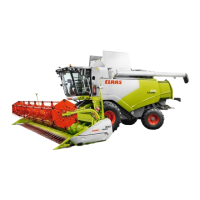
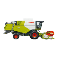
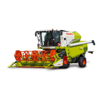
Do you have a question about the Claas TARGO K50 and is the answer not in the manual?
Provides context and scope of the repair manual contents.
Guidance on identifying the specific machine model and serial number.
General safety advice and precautions before starting maintenance.
Crucial safety directives for machine operation and maintenance.
Details on the construction of front and rear axles.
Step-by-step guide for front axle servicing procedures.
Step-by-step guide for rear axle servicing procedures.
General maintenance, dismantling, and assembly guidelines for axles.
Procedures for steering cylinder removal and overhaul.
Steps for servicing the epicyclic reduction gear components.
Procedures for wheel hub dismantling and assembly.
Procedures for servicing the axle beam trumpet and brake group.
Steps for differential group dismantling and assembly.
Instructions for assembling the brake pack and housing.
Procedures for adjusting wheel alignment and steering angles.
Common problems and solutions for axles and steering systems.
Explanation of the hydrostatic steering system's function.
Methods for verifying steering system functionality.
Procedures for removal and installation of the steering valve.
Overview and specifications of the Perkins engine.
Procedures for removing and installing the engine assembly.
Specific steps for engine removal with the pod attached.
Overview and technical specifications of the transmission system.
Detailed technical specifications for the transmission.
Diagram illustrating the gearbox components and layout.
Function of the speed sensor and methods for testing.
Details on solenoid placement and electrical connections.
How the APC module controls gear selection and displays.
Navigating and understanding the information on the transmission display.
Explanation of failure codes displayed by the system.
Schematics illustrating hydraulic circuits for different gears.
Guide to diagnosing and resolving common transmission problems.
Procedures for testing system pressures and fluid levels.
Identification and location of various ports on the transmission.
Description and operation of the telescopic boom.
Steps for removing the boom assembly from the machine.
Steps for installing the boom assembly onto the machine.
References to hydraulic manual for cylinder maintenance.
Steps to remove the boom tray cassette.
Procedure for removing the inner boom section.
Instructions for replacing wear pads on the boom.
Overview of the machine's chassis construction.
Procedures for removal and installation of the operator's cab.
Steps for removing and installing the fuel tank.
Description of the heater and air conditioning system components.
Steps for removal and installation of the blower motor.
Procedures for removal and installation of the heater coil.
Steps for removal and installation of the evaporator coil.
Procedures for removal and installation of the receiver-drier assembly.
Steps for removing the air conditioning condenser coil.
Procedures for axial fan and relay removal/installation.
Steps for compressor removal and installation.
Table detailing the physical dimensions of the machine.
Specifications for lift height, capacity, reach, and speed.
Data related to carriage movement and boom cycle times.
Technical details for engine, transmission, and tyre specifications.
Specifications for hydraulic system and fluid capacities.
| Brand | Claas |
|---|---|
| Model | TARGO K50 |
| Category | Farm Equipment |
| Language | English |