WS1 & 1.25 Man u al Page 5
Table 4 shows the order of the cycles when the valve is set up as a lter. When the control valve is used as a down ow
re gen er at ing lter, the OEM has the option to specify one backwash or two backwashes. If the control valve is set to
regenerate for a lter, the OEM has the option of having the regenerant re ll after the rinse cycle or have the regenerant pre ll
before regeneration. If the OEM chooses to have the regenerant pre ll before regeneration, the pre ll starts two hours before
the regeneration time set. During the 2-hour period in which the regenerant is being made, treated water is still available. For
example: regeneration time = 2:00 am, pre ll option selected, down ow lter. Fill occurs at 12:00 a.m., start of backwash
cycle occurs at 2:00 a.m. There is only one rinse. Backwashes can be set to normal or longer. The option selected will apply to
all backwashes. Tables 5 and 6 show the length of the cycles when the valve is set up as a lter.
2
These are reference numbers that approximate the amount of salt needed. The actual capacity in grains per pound of salt is
used in cal cu la tions.
3
Total time does not include ll time, which is dependent upon the amount of salt needed. When in the ll mode the system
is providing treated water.
When the control valve is used as a non-regenerating lter, the OEM has the option to specify one backwash or two
backwashes. If two backwashes are speci ed, two rinses occur. Tables 5 and 6 show the length of the cycles when the valve
is set up as a lter. When used as a non-regenerating lter, the down ow piston must be installed, the regenerant piston
removed, injector plugs must be installed in both the DN and UP injector locations and the re ll elbow must be replaced with
a re ll port plug.
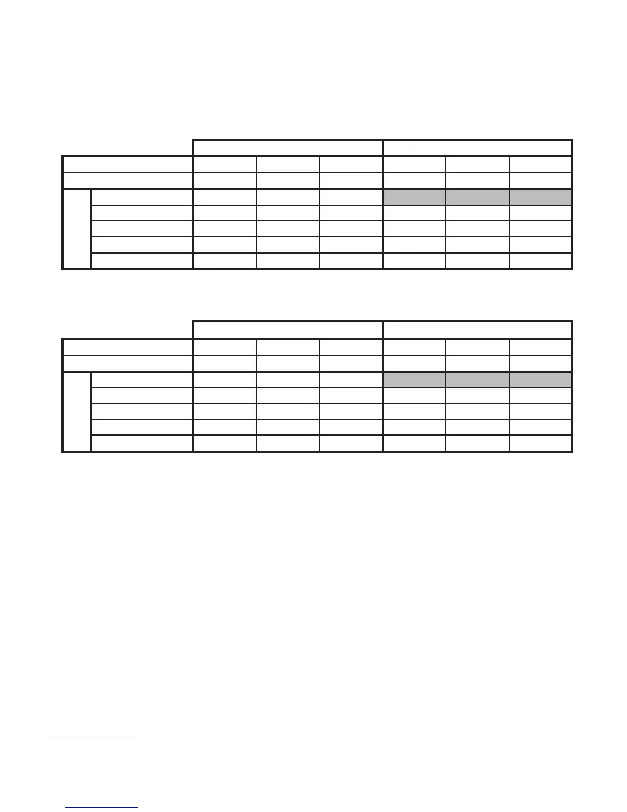
Table 2
Backwash Normal Length Softener
Cycle Times in Minutes
WS1 & WS1.25 Downfl ow Softener WS1 & WS1.25 Upfl ow Softener
Grains Capacity/lb NaCl 6000 to 3501 3500 to 2501 2500 to 1700 6000 to 3501 3500 to 2501 2500 to 1700
lbs NaCl/cu ft resin
2
Less than 7.5 7.5 to 12 More than 12 Less than 7.5 7.5 to 12 More than 12
Backwash Normal 6 8 8
Regenerate 45 60 75 45 60 75
Backwash Normal 3 8 10 6 10 12
Rinse 346346
Total
3
57 80 99 54 74 93
Cycle time
in Minutes
WS1 & WS1.25 Downfl ow Softener WS1 & WS1.25 Upfl ow Softener
Grains Capacity/lb NaCl 6000 to 3501 3500 to 2501 2500 to 1700 6000 to 3501 3500 to 2501 2500 to 1700
lbs NaCl/cu ft resin
2
Less than 7.5 7.5 to 12 More than 12 Less than 7.5 7.5 to 12 More than 12
Backwash Longer 8 10 12
Regenerate 45 60 75 60 70 80
Backwash Longer 8 10 12 12 14 16
Rinse 468579
Total
3
65 86 107 77 91 105
Cycle time
in Minutes
Table 3
Backwash Longer Length Softener
Cycle Times in Minutes
When set up as a softener the backwash and rinse cycles automatically increase with increasing salt dosage. Backwashes can
be set to be NORMAL or LONGER. The option selected will apply to all backwashes. Tables 2 and 3 show the length of the
cycles when the valve is set up as a softener.
 Loading...