6 7
English
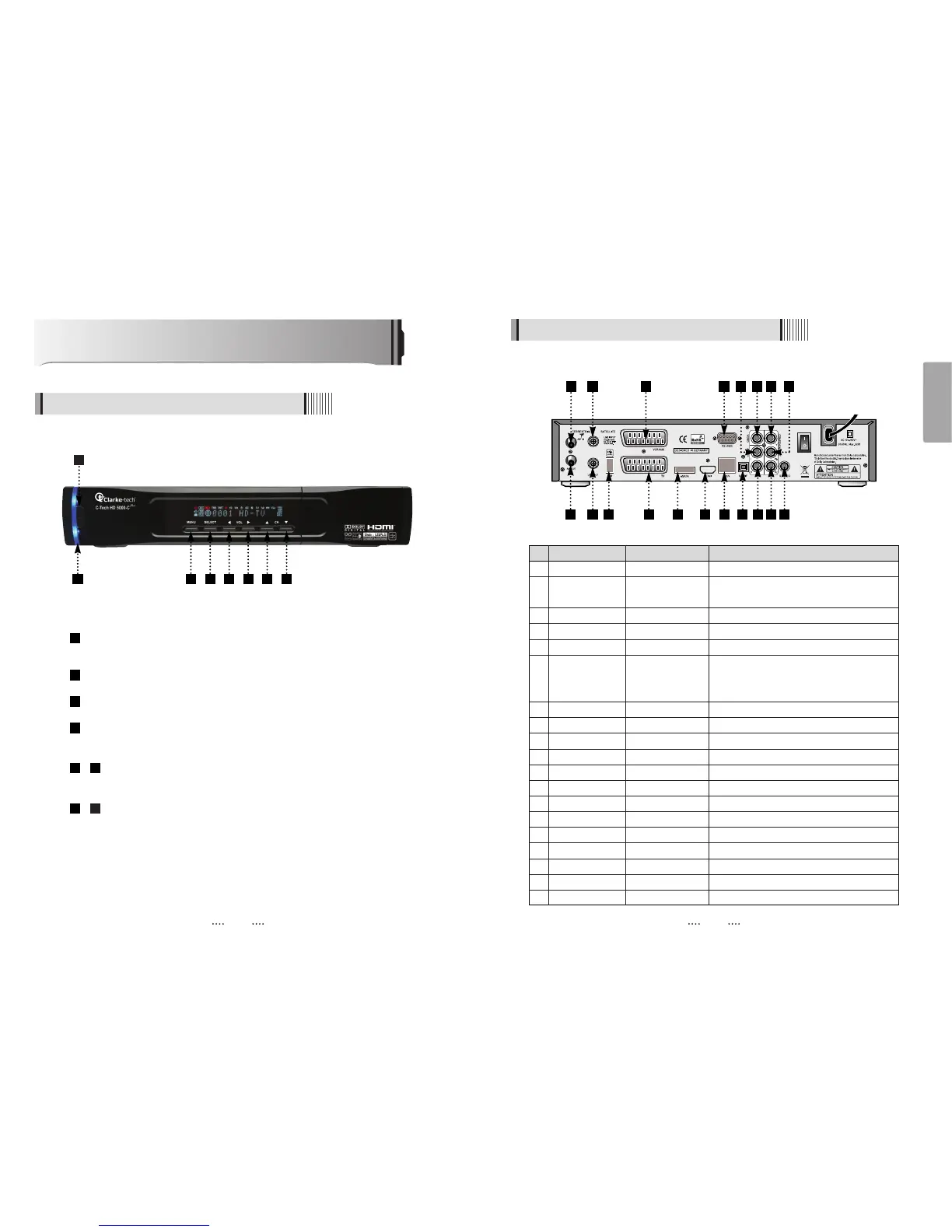
Controls/Functions
4.1 Front Panel
4.2 Rear Panel
Standby/Power on Indications Lamp : Flashes red light in “Standby” mode and
shows no light in “Power ON” mode.
Power : Switches the receiver between “Standby” and “Power ON” modes.
Menu : To enter or exit the main menu.
Select : To show the Channel List in non-menu mode and select on item or
confirm in menu mode.
- VOL
ȜȞ : To change the volume level in non-menu mode and modify
a setting in menu mode.
- CH ƌƊ : To switch channels or change the cursor position on the
application screen.
87
65
4
3
2
1
No. Name Connector Function
1 ANT IN IEC 169-2 FEMALE Input from terrestrial antenna
2 ANT OUT IEC 169-2 MALE Loop-through output from digital tuner
and Output to TV
3 LNB INPUT IEC 169-24 FEMALE IF input from LNB to digital tuner
4 LNB OUTPUT IEC 169-24 FEMALE IF loop-through output from digital tuner
5 USB USB A-type USB 2.0
6 VCR/AUX SCART SCART CVBS Video Output
CVBS, RGB Video Input
Audio Output
7 TV SCART SCART CVBS Video Output, Audio Output
8 eSATA E-SATA External SATA
9 HDMI HDMI Digital Video/Audio Output
10 RS-232C DB-9 Low speed serial port
11 LAN RJ-45 10/100Mbps Ethernet
12 S/PDIF Fiber Optic Digital audio output (Optical)
13 VIDEO RCA cinch Composite video output
14 AUDIO L RCA cinch Left audio output
15 AUDIO R RCA cinch Right audio output
16 Y RCA cinch Component video output(Y)
17 Pb RCA cinch Component video output(Pb)
18 Pr RCA cinch Component video output(Pr)
19 S-VIDEO MINI-DIN S-VHS Output
2
1 3 6
10 1314 16 17
1 3 4 5 6 7 8
2 4 5 87 9
11 12 15 18 19