Page 10 of 41
injured person permission from that person must be
received until you can help him. Unless the injury is
life threatening, move the injured person with
extreme care and then only if strictly necessary.
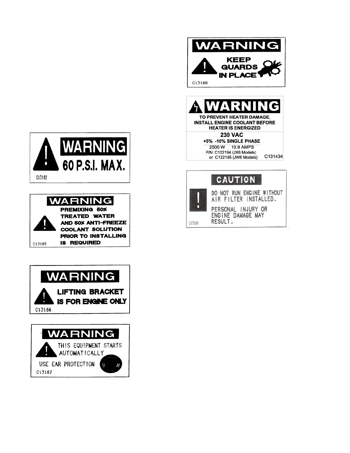
WARNING LABELS
Warning labels, in picture form, are applied to the
engine. Their meanings are given below.
Important Note: Labels that show an exclamation
mark indicate that there is a possibility of danger.
Heat Exchanger Maximum Working Pressure
Coolant Mixture
Lifting Point
Automatic Start
Rotating Parts
Jacket Water Heater Voltage
Air Filter Installation
2.0 INSTALLATION/OPERATION
2.1 TYPICAL INSTALLATION
A typical Fire Pump installation is shown in Figures
#6 & 6A.
1. Pump/Engine set
2. Main Pump Controller
3. Pump discharge
4. Air louver
5. Entrance door with air louver
6. Exhaust silencer
7. Exhaust system supports
8. Exhaust outlet pipe
9. Concrete base
10. Exhaust flexible connection joint/pipe
11. Air Discharge Duct from Radiator
NOTE: For radiator cooled engines, the total air
supply path to the pump room, which includes any
louvers or dampers, shall not restrict the flow of the
air more than 0.2” (5.1mm) water column. Likewise,
the air discharge path, which includes any louvers,
dampers, or ducting, shall not restrict the flow of air
more than 0.3” (7.6mm) water column.