Page 27 of 41
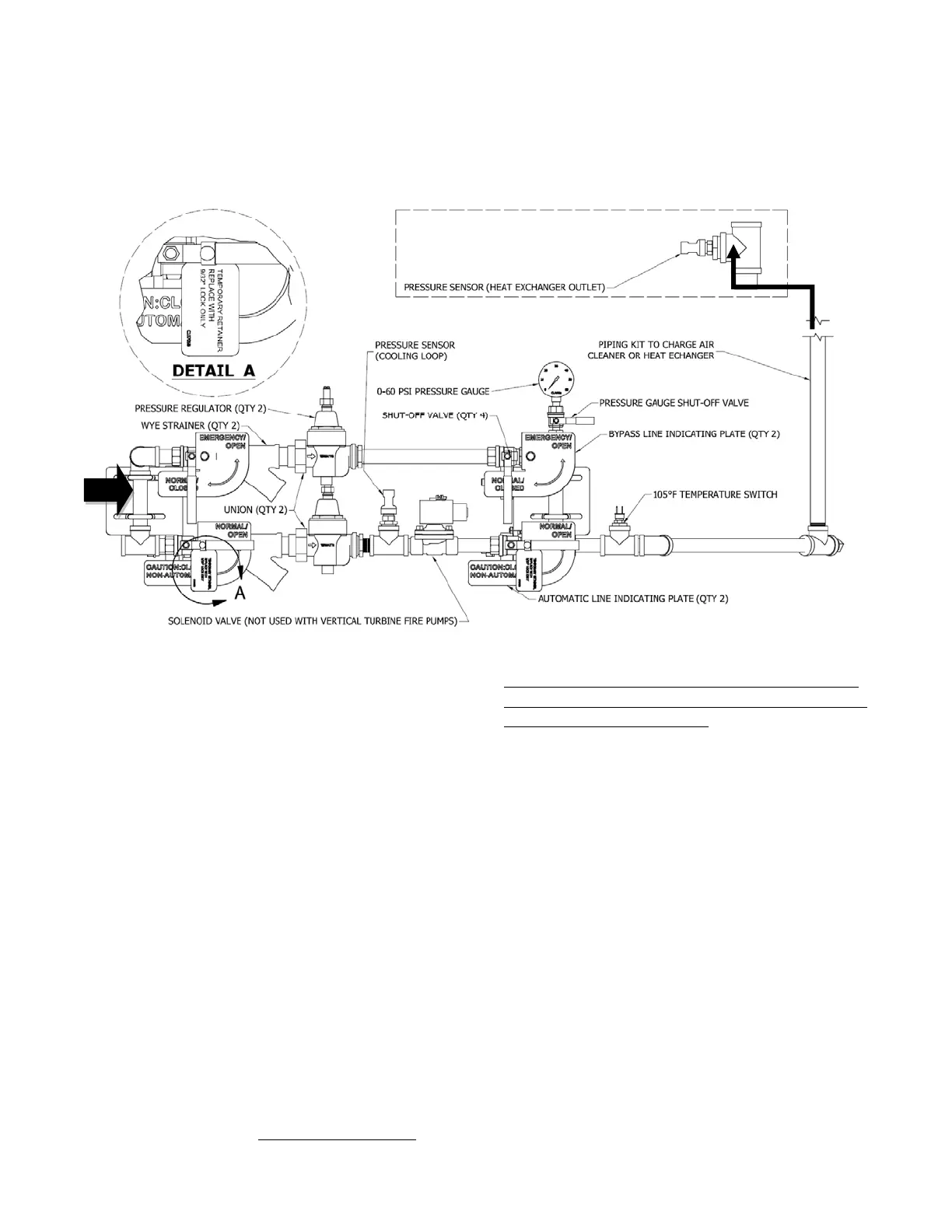
Figure #26
3.4.7.3 Setting Raw Water Flow Rate
The proper amount of raw water flow thru the engine
is of the utmost importance, and the pressure gauge
value does little to indicate if there is sufficient flow.
When the engine is exercised weekly, the amount of
raw water flow exiting the engine should always be
checked to verify it does not appear to have
diminished.
During initial commissioning of the engine, it is
important to correctly set the raw flow rate going thru
the cooling loop. Each Clarke engine model has an
Installation and Operation (I&O) Datasheet that
provides basic operating conditions of the engine and
most values are given based upon engine speed. You
will find this datasheet in the documentation bag that
is shipped with the engine for your specific Clarke
model. This datasheet must be available during
commissioning in order to set the proper minimum
raw water flow. With the fire pump flowing 150%
of rated flow, and the Automatic flow line open; set
minimum flow by using the adjusting screw at the top
of the pressure regulator. If proper cooling water
flow rate is established then no fire pump controller
alarm will be triggered to indicate clogged raw water
strainer (low raw water flow).
NOTE: To increase flow turn the adjusting screw
clockwise and to reduce flow turn the adjusting screw
counterclockwise. Do not exceed 60 psi on the
cooling loop pressure gauge!
You will need to capture the flow for a specific
amount of time coming out of the heat exchanger and
going to a floor drain in order to establish a
reasonably accurate flow rate value. Using a
container or bucket of known volume, record the time
required to fill the container and compare to the gpm
or L/min value provided on the I&O datasheet.
THIS IS CRITICAL FOR PROPER ENGINE
COOLING AT MAXIMUM PUMP LOAD! After
setting the pressure regulator in the Automatic
flowline, open the Manual by-pass line valves, and
then close the Automatic flowline valves and repeat
the above process in order to set the flowrate going
thru the pressure regulator in the Manual by-pass
line. Once this is completed; close the Manual by-