Page 14 of 41
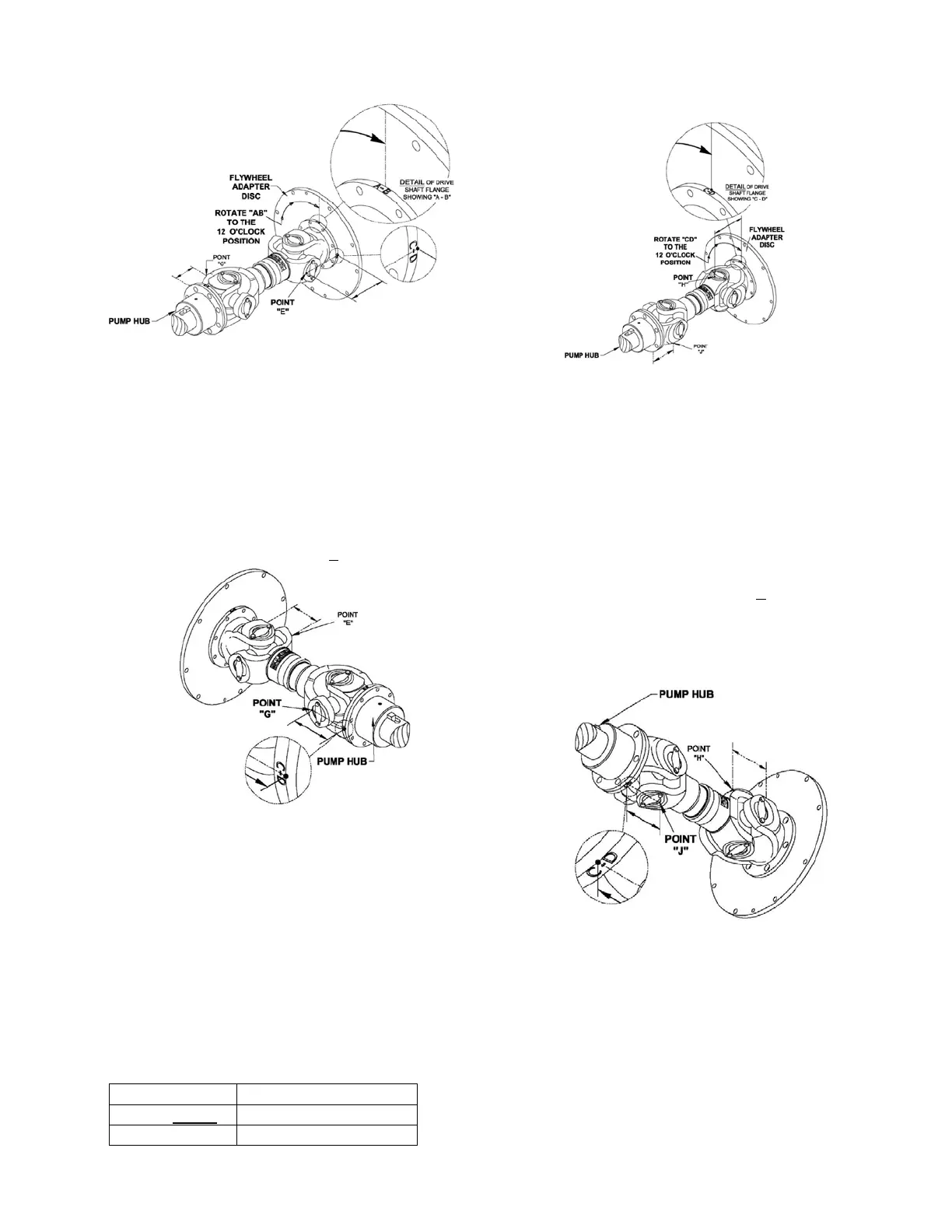
Figure #7a
B) With the driveshaft in the same orientation as
the previous step (Step A), check the
Horizontal Angular alignment of the shafts.
1. Measure from the mating surface of the
companion hub to point G shown on
figure #7b. (Point G is the furthermost
point on the bearing bore). This
measurement must be equal to the
measurement at point E + 0.5 mm.
Figure #7b
C) To check the Vertical Parallel Offset, the
driveshaft must be re-orientated.
1. Rotate the shaft 90
○
so the reference
“CD” on the flywheel adapter disc or the
circumference of the drive shaft flange
(against the flywheel) is in the position
shown on Figure#7c.
2. Measure from the face of the flywheel
adapter disc to point H. (Point H is the
furthermost point on the bearing bore
diameter). The measurement must be:
Measurement Driveshaft
70.5 ± 1 mm CDS20-S1
112.5 ± 1 mm SC81A / CDS50-SC
Figure #7c
D) With the driveshaft in the same orientation as
the previous step (Step C), check the Vertical
alignment of the shafts.
1. Measure from the mating surface of the
pump companion hub of the drive shaft
to point J as shown in figure #7d. (Point J
is the same as point G, with the
driveshaft rotated 90
o
). This
measurement must be equal to the
measurement at point H + 1 mm.
Re-install all guards and grease fittings before
reconnecting the battery cables.
Figure #7d
DRIVESHAFT MAINTENANCE
1. To service the driveshaft disconnect the
negative battery cables, remove the top of
guard an set aside.
2. Rotate engine shaft manually so the u-joint
grease fittings are accessible.
3. Using a hand held grease gun with N.L.G.I.
grade 1 or 2 grease position on grease fitting.