2.3
LAYING
OUT
THE
SYSTEM
2.3.1
PORTABLE
INSTALLATIONS
Having
determined the
number
and
type
of
remote
stations
you
wish
to use, decide
on
a location for the
main
station.
It
should
be
near a
source of
115V
AC
(power
consumption
is
app
roximately
80
watts.)
There
are
six
parallel
outputs availab
le
on
the
rear
panel of the
CS-100,
and
two
sets
of
3
parallel
outputs
on
the
CS-200.
Any
remote
sta
t ions
can
be
connected
directly
to the 6 outputs. Additionally, remote
st
at
ions
can
be
added
by
"daisy chaining"
them
to
one
another and/or
by
using the
QP-100
Quadrapuss
splitter.
Cables should
be
routed
away
from
heavy
AC
power
sources,
such
as
lighting
panels,
electric
motors,
etc.
2.3.2
PERM
'
ANENT
INSTALLATIONS
The
same
general considerations apply here
as
for
portable systems,
as
described in the preceding paragraph. Additionally, cables should
be
installed
in accordance with approved local building codes. Class II
wiring
may
be
used. Connections to
wall-plates
or wall-mount remote
stations
are
shown
in the di agrams.
2.3.3
ISOLATED
CHANNELS
The
BA-l
In-Line
Isolator
can
be
installed
anywhere
in the system.
For
example, plug
it
into
one
output connector
on
the
rear
panel of the
main
station
to create
an
entire
isolated
channel.
Alternately,
plug
it
into a remote
station
at
the
end
of a cable
run
to
isolate
further
remote
stations
while using a
minimum
of
additional interconnect cable.
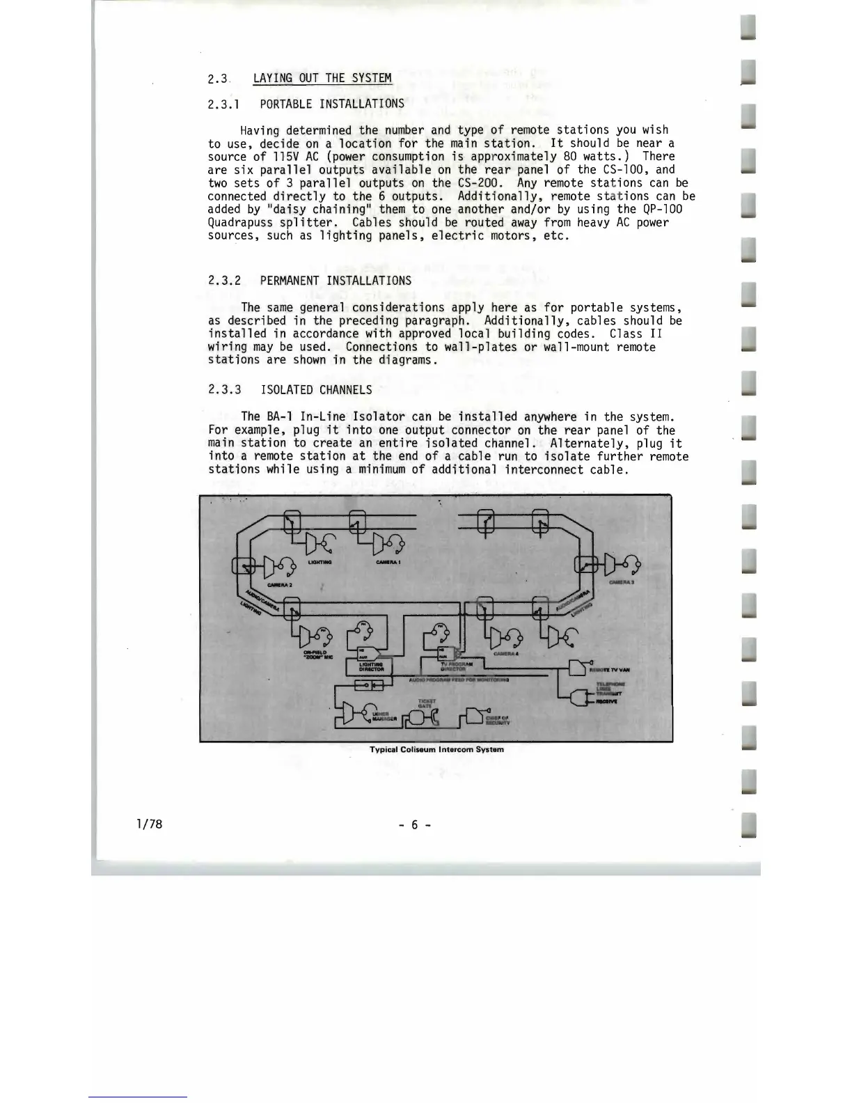
Typical
Coliseum
Intercom
System
- 6 -
1/78