General Description Chapter 1
750-177 1-3
C. Construction
Steam boilers designed for 15 psig and hot water boilers designed for 250F at 160 psi or less are constructed
in accordance with Section IV, Heating Boilers, of ASME Code. Steam boilers designed for 150 psig are
constructed in accordance with Section I, Power Boilers, of the ASME Code.
D. Steam Controls (All Fuels)
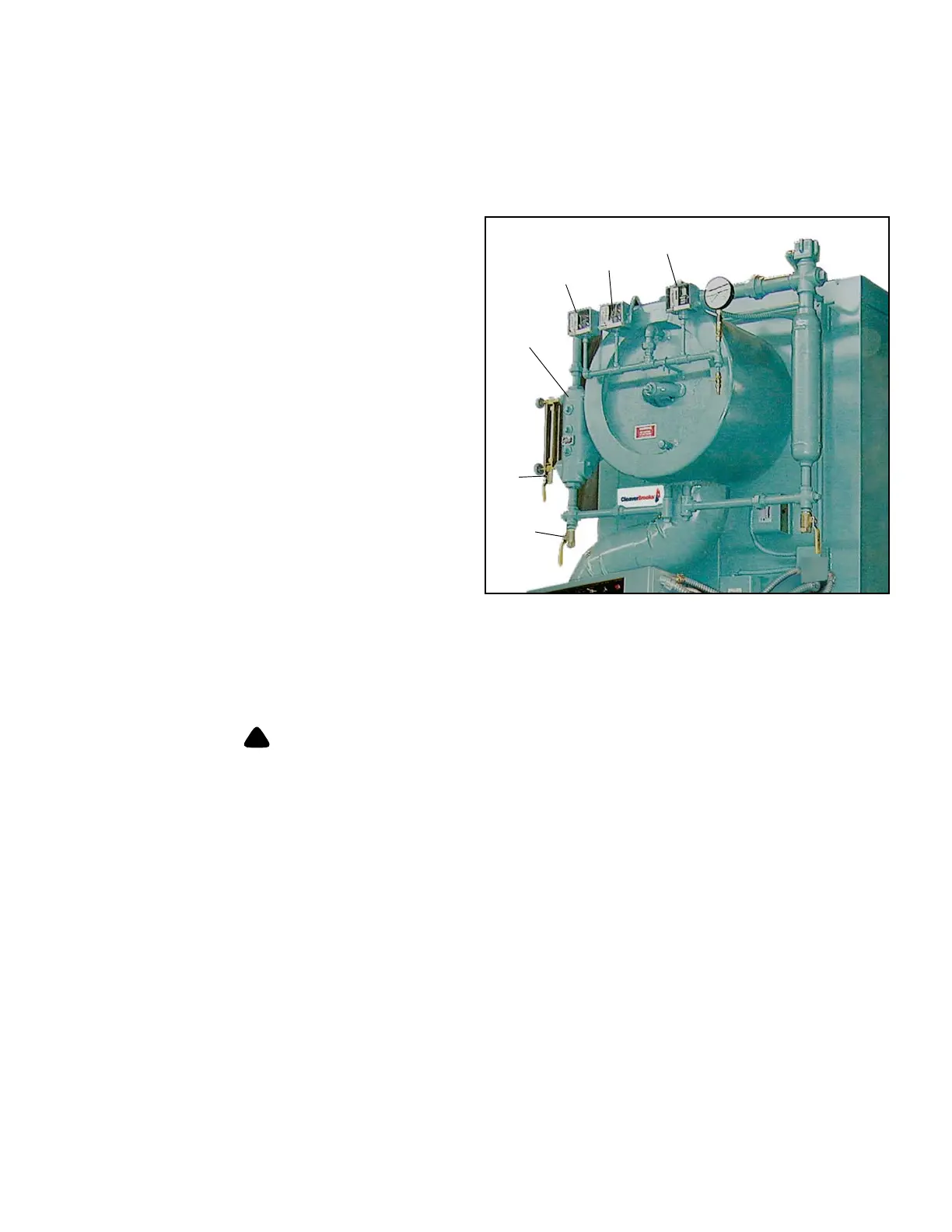
Figure 2-2: Steam Controls
1
2
3
4,5
6
7
1. High Limit Pressure Control: Breaks a circuit to
stop burner operation on a rise of pressure above a
selected setting. It is adjusted to stop the burner at
a preselected pressure above the operating limit
control setting. The high limit pressure control is
equipped with a manual reset.
2. Operating Limit Pressure Control: Breaks a circuit
to stop burner operation on
a rise of boiler pressure
at a selected setting. It is adjusted to stop or start
the burner at a preselected pressure setting.
3. Modulating Limit Pressure Control: Senses
changing b
oiler pressures and transmits the
information to the modulating motor to change the
burner firing rate when the manual-automatic
switch is set on “automatic.”
4. Low Water Cutoff and Pump Control: Float-
operated control
responds to the water level in the
boiler. It performs two distinct functions:
• Stops firing of the burner if water level lowers
be
low the safe operating point. Energizes the low-
water light in the control panel; also causes low-water alarm bell (optional equipment) to ring. Code requirements
of some models require a manual reset type of low-water cutoff.
• Starts and stops the feedwater pump (if used) to maintain water at the proper operating level.
Determine that the main and auxiliary low water cutoffs and pump control are level after installation
and throughout the equipment’s operating life. Failure to follow these instructions could result in
equipment damage.
5. Water Column Assembly: Houses the low-water cutoff and pump control and includes the water gauge glass and
gauge glass shutoff cocks.
6. Water Column Drain Valve: Provided so that the water column and
its piping can be flushed regularly to assist in
maintaining cross-connecting piping and in keeping the float bowl clean and free of sediment. A similar drain valve
is furnished with auxiliary low-water cutoff for the same purpose.
7. Gauge Glass Drain Valve: Provide
d to flush the gauge glass.
A
B