Chapter 2 Profire V Burner
2-40 750-177
FULL MODULATION COMBINATION GAS-OIL BURNER ADJUSTMENT
1. Set the “MANUAL-AUTO” switch to the “MANUAL” position.
2. Position the manual flame control potentiometer in the
“CLOSED” (low-fire) position.
3. Turn the fuel selector switch to the “OIL
” position.
4. Turn the burner switch to the “ON” position.
5. Proceed with startup and adjustments using the same p
rocedures as explained above for oil burners.
6. After the system has been completely adjusted for oil firing,
place the burner switch to “OFF” andposition the fuel
selector switch to “GAS”.
7. Proceed with startup and adjustments using the same procedu
res as explained above for gas burners. Do not alter
the air settings set for oil. Correct the O2 levels by adjusting the butterfly valve.
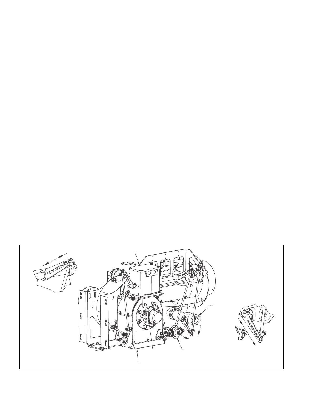
K. Modulation Control
LINKAGE CONTROL ADJUSTMENT
The linkage consists of adjustable cams, levers, rods and ball joints that transmit motion from the modulating
motor to the air damper
, gas butterfly valve and oil metering unit. When properly adjusted, coordinated
movement of the air and fuel control devices provide proper fuel-air ratios through the firing range. In linkage
adjustments, several important factors serve as guides:
• The modulating motor must be able to complete its full travel range. Restrictions will damage the motor and/or linkage.
• Lever and rod adjustments should be made
with the motor in low-fire position.
The modulating motor will be stopped at the end of its stroke by an internal limit switch. Combustion gas
analysis indicates the air to fuel ratio and the degree of complete combustion. The closer the rod comes to
parallel with the lever, the slower the rod moves. The angles of the driven levers on the jackshaft can be
adjusted to vary the rate of change. The closer the rod to the hub of the lever, the less distance it will travel.
Increasing the lever length on the damper, metering unit and valve(s) decreases flow rate.
A
B
TYPICAL LINKAGE
ADJUSTMENT
"DRIVING"
GAS VOLUME
CONTROL
VALVE
FUEL OIL
UNIT
OIL
METERING
VALVE
AIR INLET
HOUSING
MODULATING
MOTOR
DECREASE
TYPICAL LINKAGE
ADJUSTMENT
"DRIVEN"
INCREASE
DECREASE
INCREASE
Figure 2-25: Linkage Adjustment