Profire V Burner Chapter 2
750-177 2-41
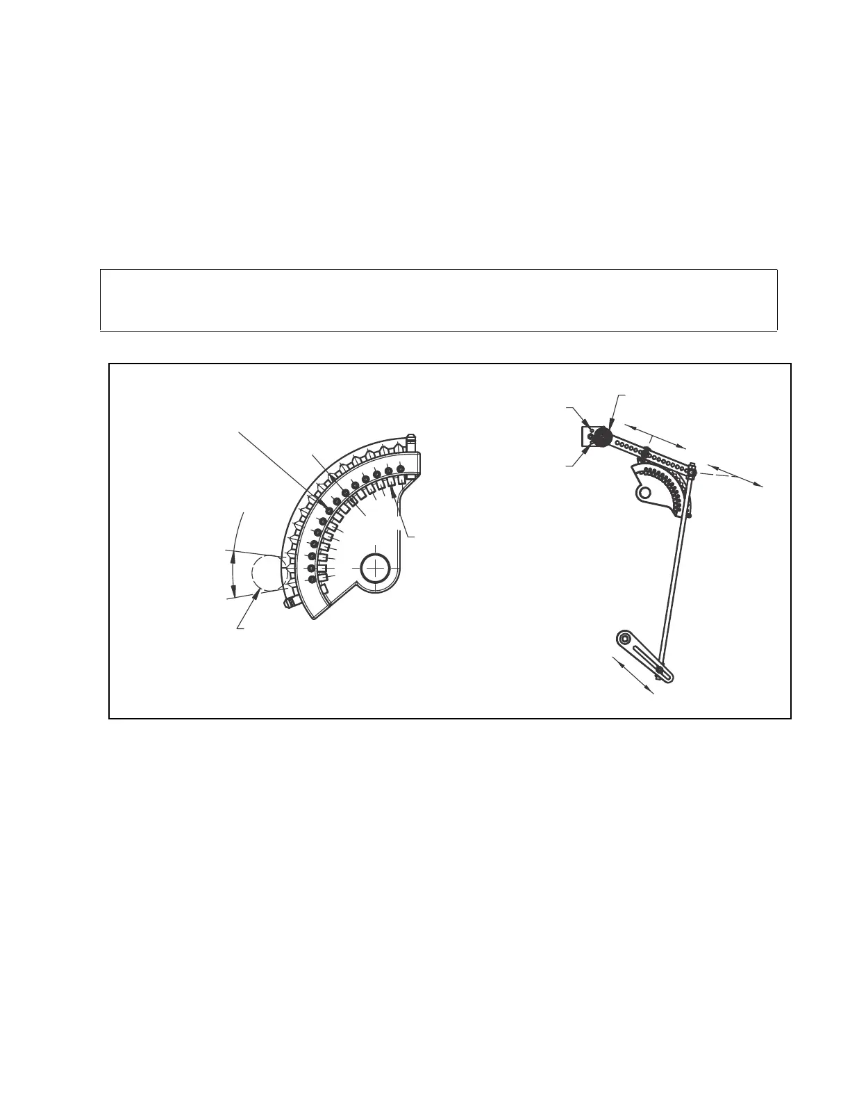
CAM TRIM ADJUSTMENT
After low and high-fire adjustments are complete, final adjustment is
made with the cam assembly to obtain
a good air-fuel ratio throughout the entire firing range. The input of combustion air is fixed at any given point
in the modulating cycle. The fuel input may be varied to obtain correct flue gas readings. The adjustment is
made to the metering cam by means of the 14 adjusting screws which are turned in (clockwise from the hex-
socket end) to increase the flow of fuel, and out (counterclockwise from the hex-socket end) to decrease it. A
3/32” hex key is required. It will be necessary to cut off the short end of a hex key to approximately 3/8” to
adjust the first two socket head setscrews at the low-fire position. Take a combustionan alysis at various points
of the cam profile. Adjustment can be made without cycling the burner, then operate the automatic modulating
cycle to assure satisfactory results. Tighten the locking setscrews.
NOTE: It is essential that the cam spring, cam follower bearing wheel, and cam follower arm at the pivot
point be greased sparingly every month to ensure smooth operation of the cam assembly. Regular automo-
tive bearing grease should be used.
LOW FIRE START POSITION
OF ROLLER GUIDE MUST FALL
WITHIN THESE LIMITS
ROLLER GUIDE
CAM SETPOINT
ADJUSTMENT
SCREWS
SETPOINT
LOCKING
SCREWS
INCREASE
DECREASE
RETURN
SPRING
LESS
SPRING
TENSION
MORE
SPRING
TENSION
INCREASE
DECREASE
DECREASE
DECREASE
INCREASE
INCREASE
Figure 2-26: Cam Trim Adjustment
PARALLEL POSITIONING ADJUSTMENT
For parallel positioning systems refer to the controls documentation and
to the accompanying wiring diagram
for information on adjusting the system. For C-B Hawk systems, see the following manuals:
Hawk 1000 — 750-366
Hawk 4000 — 750-342
In a properly tuned parallel positioning system the independent actuators for fuel,
air, and FGR (if so equipped)
will be coordinated to provide optimum combustion throughout the firing range.