Chapter 1 General Description
1-4 750-177
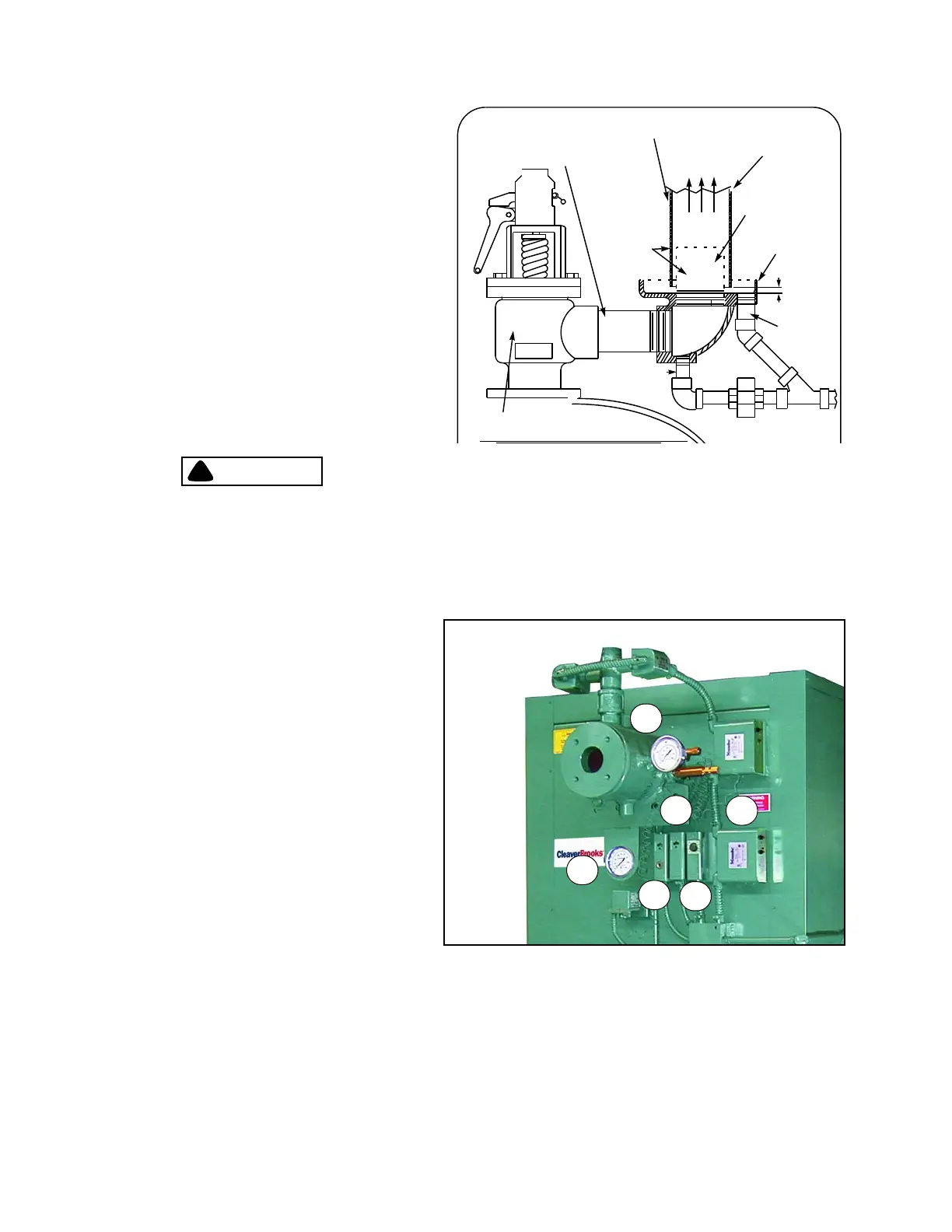
8. Safety Valve(s): Prevent buildup over the design
pressure of the pressure vessel. The size, rating and
number of valves on a boiler is determined by the
ASME Boiler Code. The safety valves and the discharge
piping are to be installed to conform to the ASME code
requirements. The installation of a valve is of primary
importance to its service life. A valve must be mounted
in a vertical position so that discharge piping and
code-required drains can be properly piped to prevent
buildup of back pressure and accumulation of foreign
material around the valve seat area. Apply only a
moderate amount of pipe compound to male threads
and avoid overtightening, which can distort the seats.
Use only flat-jawed wrenches on the flats provided.
When installing a flange-connected valve, use a new
gasket and draw the mounting bolts down evenly. Do
not install or remove side outlet valves by using a pipe
or wrench in the outlet.
DISCHARGE OPENING MUST BE
EQUAL TO OR LARGER THAN
INLET
CAUTION -
VENT PIPE
MUST NOT
TOUCH DRIP
PAN EXTEN-
SION
SUPPORT FROM BUILDING
CONSTRUCTION
VENT
DRIP PAN
EXTENSION
DRIP PAN
AND ELBOW
DRIP PAN
DRAIN
VENT PIPE
OPEN DRAIN
TO WASTE
BOILER SHELL
SAFETY VALVE
DRIP ELL DRAIN
WATER LEVEL
NOTICE: BACK-PRESSURE OF STEAM
EXHAUST SYSTEM MUST BE LESS THAN 6%
OF SAFETY VALVE SETTING.
TO STEAM
1 1/2”
MIN.
Figure 2-3: Recommended piping for steam relief
valve (not furnished by Cleaver-Brooks)
Only properly certified personnel such as the safety
valve manufacturer’s certified representative can
adjust or repair the boiler safety valves. Failure to
follow these instructions could result in serious
personal injury or death
E. Hot Water Controls (All Fuels)
Figure 2-4: Hot Water Controls
1
2
3
4
5
6
1. Water Temperature Gauge: Indicates the boiler
internal water pressure.
2. Water Pressure Gauge: Indicates the internal
pressure of the
boiler.
3. High Limit Temperature Control: Breaks a circuit to
stop bu
rner operation on a rise of temperature at a
selected setting. It is adjusted to stop burner at a
preselected temperature above the operating control
setting. The high limit temperature control is
equipped with a manual reset.
4. Operating Limit Temperature Control: Breaks a
cir
cuit to stop burner operation on a rise of boiler
temperature at a selected setting. It is adjusted to
stop or start the burner at a preselected operating
temperature.
5. Modulating Temperature Control: Senses changing
boiler
water temperature and transmits the
information to the modulating motor to change the
burner firing rate when the manual-automatic switch
is set on “automatic.”
6. Low Water Cutoff: Breaks the circuit to s
top burner operation if the water level in the boiler drops below safe operating
point, activating low-water light and optional alarm bell if burner is so equipped.