Prometha™ Installation
750-441
4
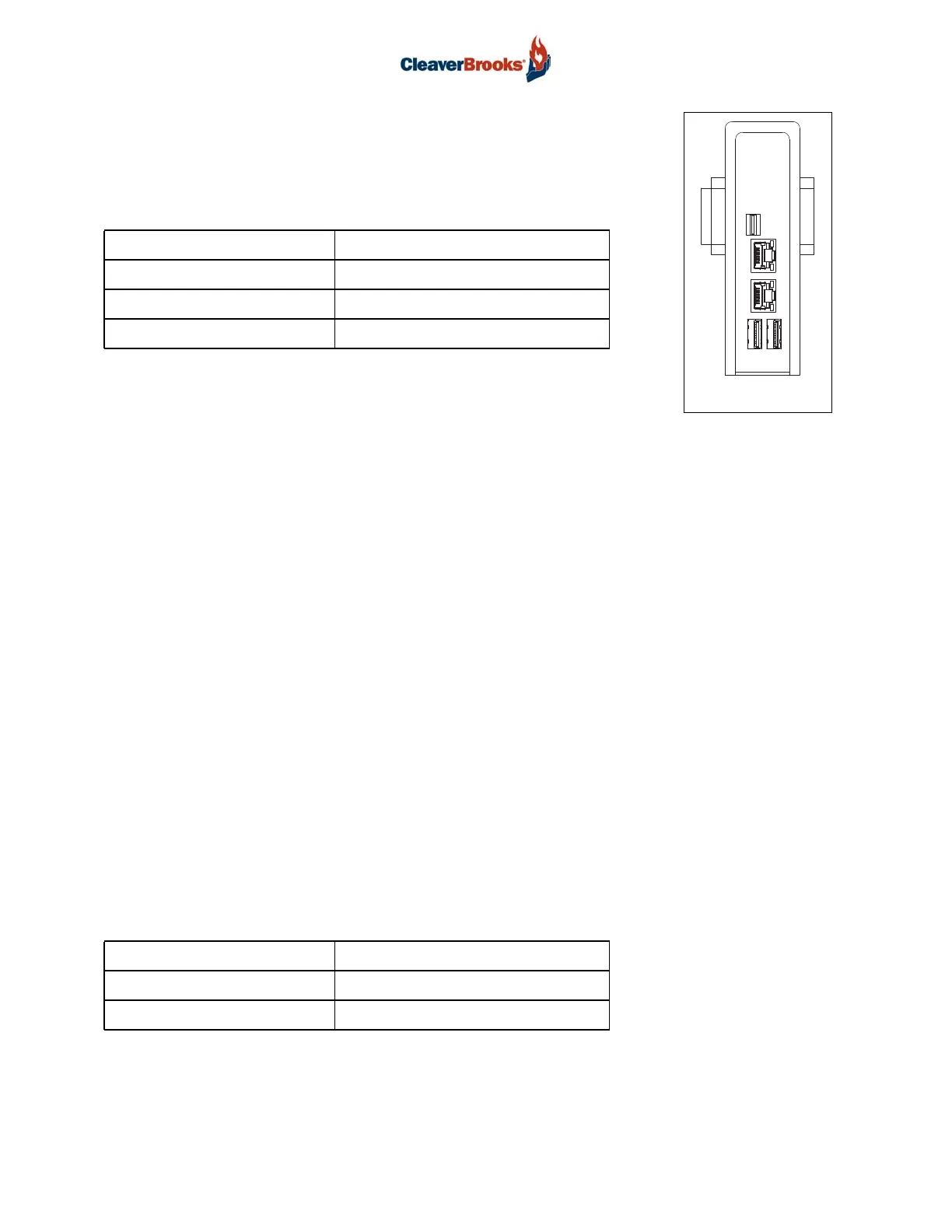
4.2 - Data Transfer Gateway
Mount the gateway on the DIN rail with the coaxial antenna connectors at the
top and the power supply connection at the bottom.
4.3 - 12VDC Power Cable
Insert the plug end into the power supply connection at the bottom of the Gateway. Connect the red
wire to the top, load side terminal of the 24V fuse holder. Connect the black wire to the top terminal
of the blue terminal block.
4.4 - LTE Antenna
The antenna should be mounted on the top, horizontal exterior surface of a Hawk panel, master
panel, DT panel or PT panel. If necessary, mounting the antenna on the side, vertical exterior surface
of these enclosures is an option as well. When choosing a mounting location, maintain as much
clearance as possible from external obstructions. The distance between the gateway and the antenna
cannot exceed 9.8 ft (3 meters), the length of the antenna leads. To install:
1. Use a 7/8” hole saw to drill a hole through the panel for the antenna cable outlet. Collect the drill
shavings in a container for later disposal. Take care not to allow drill shavings to fall inside the
panel.
2. Prepare the panel surface by wiping the installation area clean with an alcohol wipe.
3. Pass the antenna leads through the hole and remove the backing from the adhesive tape on the
underside of the antenna.
4. Attach antenna to the panel.
5. Attach the washer and nut to the threaded mounting stud. Recommended torque for mounting is
21.7 ft·lb (29.4 N·m), not to exceed 28.9 ft·lb (39.2 N·m).
The antenna cables should be routed away from 120VAC wiring wherever possible. Attach cable
MIMO2/LTE2 to the BLUE Gateway coaxial connector and MIMO1/LTE1 to the RED connector. Bun-
dle and tie excess cable lengths and attach to the panel with adhesive tie mounts.
INPUT VOLTAGE 12VDC
GATEWAY DIMENSIONS 1.3"W x 4.6"H x 3.3"D
INSTALLATION CLEARANCES 2" fin side clearance
TEMPERATURE RANGE 32degF to 122degF
ANTENNA DIMENSIONS 8.5"L x 3.7"W x 1.2"H
TEMPERATURE RANGE -40degF to 185degF
INGRESS PROTECTION IP67
GATEWAY