Do you have a question about the Clevo N950TP6 and is the answer not in the manual?
Provides information needed to service or upgrade the N950TP6 / N957TP6 notebook computer.
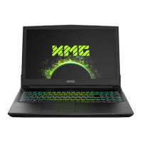
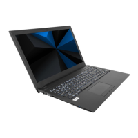
Details the technical specifications of the notebook computer, including processor, memory, storage, and video adapter.
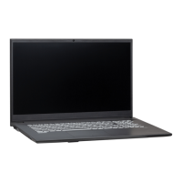
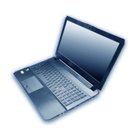
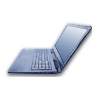
Identifies and describes the location of external ports and components on the notebook's top, front, side, and bottom views.
Details the key parts and connectors on the top and bottom views of the mainboard.
Provides step-by-step instructions for disassembling and reassembling notebook parts and subsystems.
Outlines essential maintenance tools, connection types, and safety precautions for handling computer components.
Lists the disassembly steps for various components and the corresponding page numbers for detailed instructions.
Provides detailed, step-by-step instructions for removing specific components like the battery, HDD, keyboard, processor, RAM, M.2 SSD, WLAN, and CCD.
Indicates the pages where illustrations for specific notebook parts (Top, Bottom, Main Board, LCD, HDD) can be found.
Provides detailed illustrations and part numbers for the notebook's top, bottom, main board, LCD, and HDD components.
Presents a high-level overview of the notebook's system architecture, showing major components and their interconnections.
Details the pin assignments and connections for the CPU, covering multiple sheets for comprehensive coverage.
Illustrates the connections and pin assignments for DDR4 memory modules (Channel A and Channel B).
Provides schematic diagrams for the VGA PCI Express interface and frame buffer partitions.
Details power sequences and voltage rails for various components including NVIDIA GPU, PCH, and core system power.
Illustrates the schematic diagrams for various interfaces like mDP, HDMI, USB, LAN, Audio, and KBC.
Provides schematic diagrams for the PCH (Platform Controller Hub) interfaces, covering various subsystems like PCIe, SATA, and USB.
Guides users through downloading, preparing, and executing the BIOS update process from external media.
Explains how to restart the computer after a BIOS update, enter BIOS settings, load defaults, and save changes.
| Operating System | Windows 10 |
|---|---|
| Weight | 2.5 kg |
| RAM | Up to 32GB DDR4 |
| Display Size | 15.6 inches |
| Display Resolution | 1920 x 1080 pixels |
| Ports | HDMI, Mini DisplayPort, Ethernet |