10
WATER-SOURCE HEAT PUMPS
ATA11U03
Rev.:09/16/13
Timers—Thereareseveraltimerswhichinuencethe
thermostat’soperationthatarelistedbelow.Ifanyofthe
timersispreventingtheequipmentfromturningon,the
“on”iconwillash.
Five-Minute Compressor Timeguard — This timer
preventstheY1outputfromturningonunlessithasbeen
offfor5minutes.(Option07settoOF)
Afterapowercycle,arandomizeddelaywillbeadded
toendofthetimeguardtimertopreventmultipleunits
fromhittingthepowergridallatthesametime.The
randomizationtimerwillbebetweenzeroandve
minutes.Ifademandexists,compressoroutputswill
energizebetween5and10minutesafterthepower
cycle.Itcanbedefeatedbysimultaneouslypressingthe
fanandupkeys.
Minimum On Timer —Oncetheequipmenthasbeen
turnedon,itmustremainonfor3minutes.Achangein
modeorsetpointwillcancelthistimer.
Cycle Timer—Thenumberofequipmentcyclesperhour
isdeterminedbycongurationOption16.Basedonthe
selectionof4,6or8cyclesperhour,thistimerissetto
15,10or8minutes.Thismuchtimemustelapsefromthe
startofonecyclebeforeanothercyclecanstart,imposing
thecyclesperhourlimits.Itcanbedefeatedforonecycle
bysimultaneouslypressingthefanandupkeys.
TROUBLESHOOTING
Therearethreesystemerrormessagesthatmayappear
onthethermostatscreenindicatingaproblemwith
thethermostat’soperation.Seetextbelowforpossible
system error messages and their meaning.
Space Temperature Sensor Failure — If the room
temperaturesensorfails,thetemperaturedisplaywill
show“--”(twodashes).Ifthespacetemperatureis
theaverageofboththelocalandremotesensors(as
conguredinOption5),andoneofthesensorsfails,the
thermostatprovidescontroltothevalidsensoronly.The
displaywillalternateevery10secondsbetween“--”for
the invalid sensor and the reading from the valid sensor.
Memory Failure —Ifthereisaninternalmemoryfailure,
thetemperaturedisplaywillshow“E4,”thethermostat
needstobereplaced.
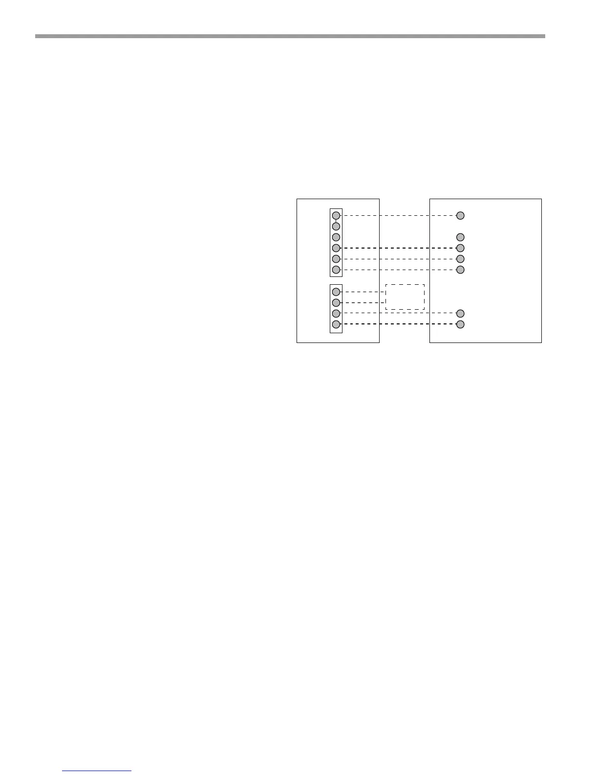
WIRING DIAGRAMS
SystemwiringdiagramisshownfortypicalClimateMaster
heatpumpunit.SeeFig.7.
OisEnergizedforcooling
Gislowspeedfan
G2ishispeedfan
Figure 7: Typical Wiring Diagram - Heat Pump
Rc
Rh
W
C
G
G2
R
W OR W1
C
G
H (DXM ONLY)
O
Y or Y1
NOTE 1
NOTE 2
S2
S1
O
Y1
THERMOSTAT
HEAT PUMP
CXM/DXM
HEAT PUMP
REMOTE
SENSOR
(Optional)
 Loading...