35
Electrical connections
in-out” topology. Dierent topologies are not
allowed (star or ring-type, etc.).
– The serial line must be laid by personnel trained
and qualified in data communication networks.
Connecting the shield
– For the bus network, use 0.75 mm
3
3-pole shielded
cables. Using other types of cables may result in
interference or malfunctions.
– The shield of the bus cable used for serial
communication must be connected to an earth
free from interference.
– The shield must be earthed at one point only.
– The continuity of the shield must be ensured the
entire length of the bus cable.
l
WARNING
These requirements are generally valid. In
some areas characterised by the presence
of particular types of EMI coupling, a dierent
type of connection of the shield may be
required.
a
CAUTION
Make sure that the metal braiding of the cables
does not touch any live points.
Use dedicated wire terminals.
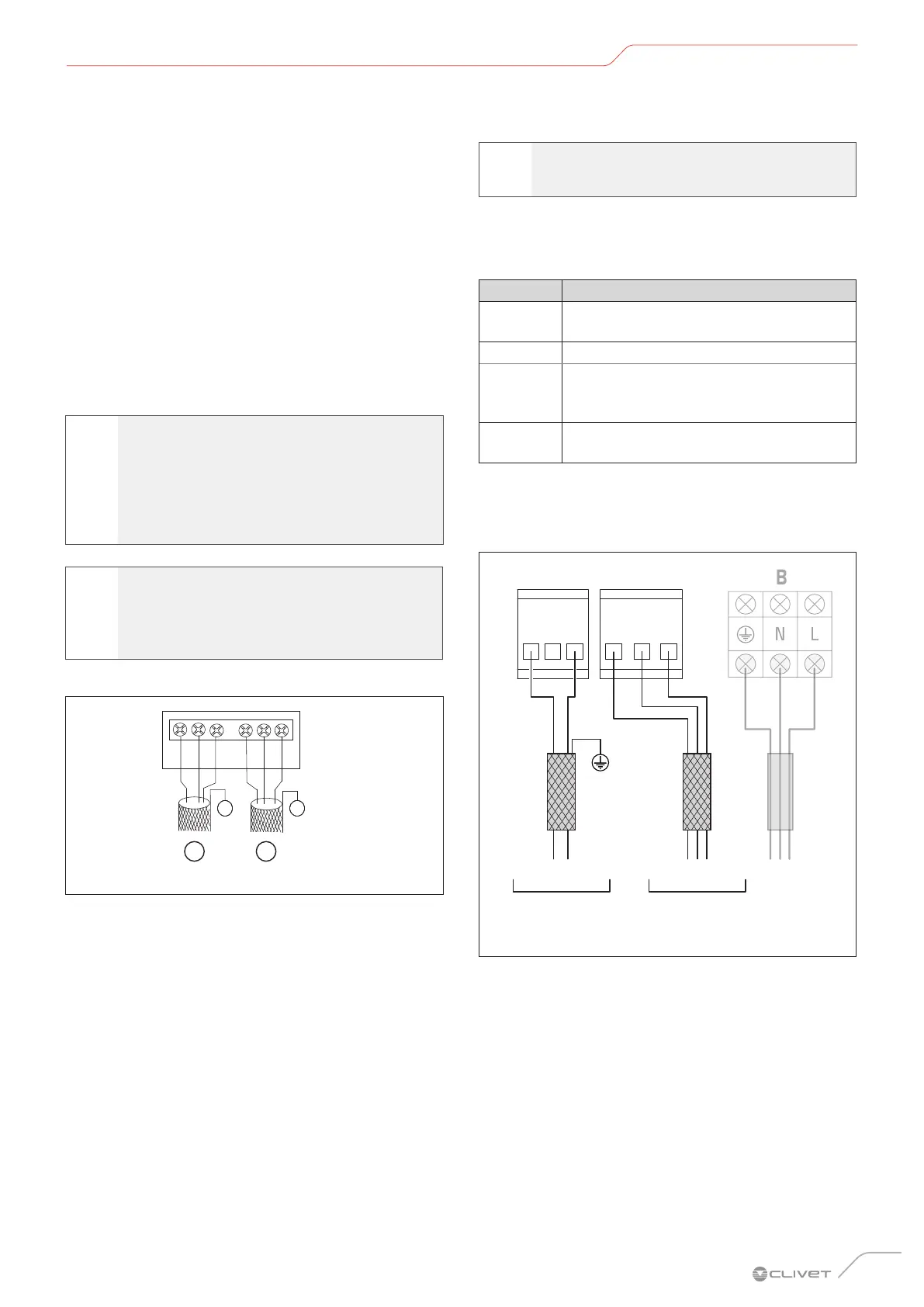
Outdoor unit connections
A B
⏚ ⏚
E P Q EX Y
Fig. 53
A To the main control board
B Indoor unit communication bus
A wrong connection can cause malfunctions. Electrical
connections: seal the electrical connections with
insulating material to prevent condensate from forming.
a
CAUTION
Do not earth communication cables P and Q.
The shielding networks of the communication cables
must be connected together and earthed. For earthing,
join the adjacent metal casing with terminals P, Q, E of the
electrical panel of the outdoor unit.
Terminals Connection
K1 K2 E
Centralised monitoring of the outdoor unit
(*)
O A E Digital energy meter
X Y E
Centralised control unit of the indoor unit
(and of the outdoor unit if K1 K2 E is not
present)
P Q E
Connection between indoor units and the
main outdoor unit
(*) if not present, the monitoring function of the outdoor unit is
integrated in the terminal block X Y E.
Indoor unit
connections
X1
X2
P
Q (E)
Segnale (BUS) Segnale (BUS)
alla morsettiera
del controllo a filo
dalla morsettiera
dell’unità esterna
Fig. 54
A Communication bus
B Power supply
C Wired controller
The dedicated function of the wired controller is shown
in the diagram with a dotted line, indicating that users can
only buy it when it is required.
Use a 3-conductor shielded cable and connect the
shielded layer to earth.
– The signal cable is 3-conductor, polarised. Use a
3-conductor shielded cable to avoid interference.
Put the closed end of the shielded cable on the
ground and open (insulate) the end. The shielding
must be earthed at one point free of interference.
 Loading...