34
Electrical connections
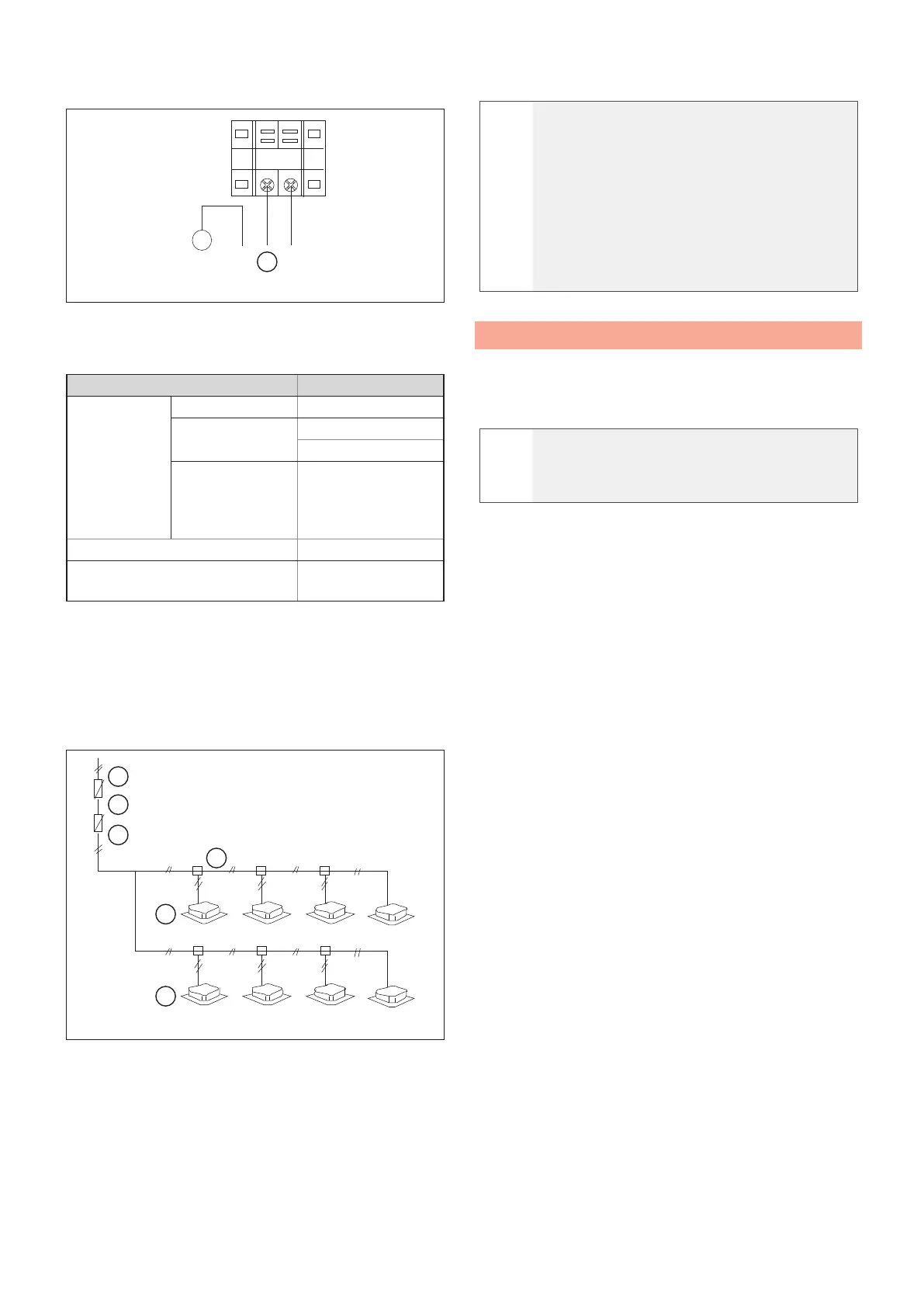
Indoor unit connections
A
L
y/g
N
⏚
Fig. 51
A Power supply
Power supply specifications
Cooling capacity (kW) 1.8~16
Indoor unit
power supply
Phase Single phase
Voltage and
frequency
220-240V~ 50Hz
220-230 V~ 60 Hz
Power cable size
(mm
2
)
The cable cross sections
must comply with the
provisions of the locally
applicable standards
Circuit switch (A) 16
Indoor unit/outdoor unit signal cable
(mm
2
) (weak electrical signal)
3-conductor shiel-
ded cable 3X0.75
Note: The diameter and length of the unbroken wires
refer to conditions of voltage fluctuations of less than
2%. If the unbroken length of the line exceeds the value
indicated, choose the cable diameter according to
applicable standards.
How to connect the indoor unit
w
A
B
C
E
E
D
Fig. 52
A Indoor unit power supply
B Circuit switch
C Manual switch
D Electrical distribution box
E Indoor unit
a
CAUTION
The refrigerant pipes, the signal wires
connecting the indoor units and the cables
connecting the indoor units to the outdoor unit
are in the same system.
If the power cable is parallel to the signal line,
install them in separate distribution ducts and
leave enough space. (Reference distance:
300 mm when the current rating of the power
cable is less than 10 A, or 500 mm for 50 A).
5.3 Communication bus network
The cables of the bus network (transmission line) must
be laid in such a way as to avoid electromagnetic
interference.
a
CAUTION
Do not lay transmission and power cables in
the same conduit.
Connect the cables as follows:
– The combinations between internal and
external sections must be the same in terms
of the refrigeration connections and electrical
connections.
– Use the “in and out” type of connection even if the
lines work with connection in parallel.
– In case of connection with a controller of a higher
level (centraliser), a transmission line is required
between each external line.
– Do not connect the power cables to the terminal
block of the bus network.
– Do not perform joints but only carry out soldering
using a heat shrink sheath. Respect the lengths
indicated in the technical manuals.
– Shunt boxes are not allowed.
– Correctly address the components of the system.
– The cable used must be of a type suitable for data
transmission with RS 485. If not suitable for such
use it can cause interference and diculties in the
transmission of packets.
– The insulation and voltage characteristics of the
cable must be in accordance with the electrical
regulations in force.
– The insulation of the cable must have flame or fire
retarding characteristics, commensurate with the
electrical standards of reference for the type of
system used.
– The cable must be laid to standard.
– The cable must be laid separately from other
cables, especially from power cables or from
cables of dierent voltages.
– The cable must be laid far from cables or devices
that can cause electromagnetic interference.
– The RS485 serial line must always be of the “Bus
 Loading...