3
Summary
1. Power range and furniture ................................................................................... 5
1.1 Power ........................................................................................................................... 5
1.2 Furniture ...................................................................................................................... 5
2. Layout of components .......................................................................................... 6
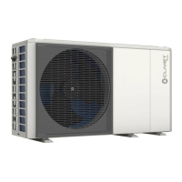
2.1 Sizes 2.1 - 3.1 ............................................................................................................... 6
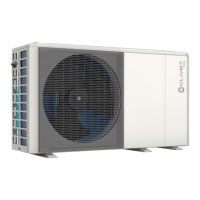
2.2 Sizes 4.1 - 5.1 ............................................................................................................... 7
2.3 Sizes 6.1T - 7.1T - 8.1T ................................................................................................ 8
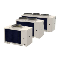
2.4 Sizes 9.1 - 10.1 - 12.1 - 14.1 .......................................................................................... 9
3. Refrigeration circuit ............................................................................................... 10
3.1 Refrigerant circuit diagram ..................................................................................... 10
3.2 Heating and Domestic Hot Water operation ..................................................... 12
3.3 Cooling and defrosting operation ........................................................................ 12
4. Control .................................................................................................................... 13
4.1 Stop .............................................................................................................................. 13
4.2 Standby ....................................................................................................................... 13
4.3 Startup control ........................................................................................................... 13
4.4 Startup in heating and domestic hot water mode ........................................... 16
4.5 Startup in cooling mode .......................................................................................... 16
4.6 Normal operation ...................................................................................................... 17
4.7 Protection control ..................................................................................................... 19
4.8 Special controls ......................................................................................................... 23
5. Layout of electrical panel ..................................................................................... 31
5.1 Sizes 2.1 - 3.1 ............................................................................................................... 31
5.2 Sizes 4.1 - 5.1 ............................................................................................................... 31
5.3 Sizes 6.1 - 7.1 - 8.1 ....................................................................................................... 32
5.4 Sizes 6.1T - 7.1T - 8.1T ................................................................................................ 32
5.5 Sizes 9.1 - 10.1 - 12.1 - 14.1 .......................................................................................... 33
6. Layout of PCB boards ........................................................................................... 34
6.1 Water circuit board 2.1 - 14.1 .................................................................................... 34
6.2 Refrigerant circuit board - 21.- 3.1 - 4.1 - 5.1 ......................................................... 36
6.3 Refrigerant circuit module 6.1 - 7.1 - 8.1 single-phase ....................................... 38
6.4 Refrigerant circuit module 6.1T - 7.1T - 8.1T ......................................................... 40
6.5 Refrigerant circuit module 9.1 - 10.1 - 12.1 - 14.1 ................................................... 42
6.6 Inverter module - 2.1. - 3.1 ....................................................................................... 44
6.7 Inverter module - 4.1. - 5.1 ....................................................................................... 45
6.8 Inverter module - 6.1. - 7.1 - 8.1 single-phase ...................................................... 46
6.9 Inverter module - 6.1.T - 7.1T - 8.1T ......................................................................... 47
6.10 Inverter module - 9.1. - 10.1 - 12.1 - 14.1 ................................................................... 48
6.11 Filter module 6.1T - 7.1T - 8.1T ................................................................................. 49
6.12 Filter module - 9.1. - 10.1 - 12.1 - 14.1 ........................................................................ 50
6.13 Display ......................................................................................................................... 51
6.14 DIP Switch setting ..................................................................................................... 51
7. Table of error codes .............................................................................................. 53
8. Troubleshooting ..................................................................................................... 55
9. Temperature sensor resistance characteristics ................................................ 114
 Loading...