10
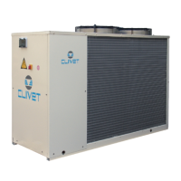
4.7 RECOMMENDED CONNECTION
4 - WATER CONNECTIONS
P
9
11
14
8
F
2
3
5
12
7
6
4
8
1
10
13
P
7
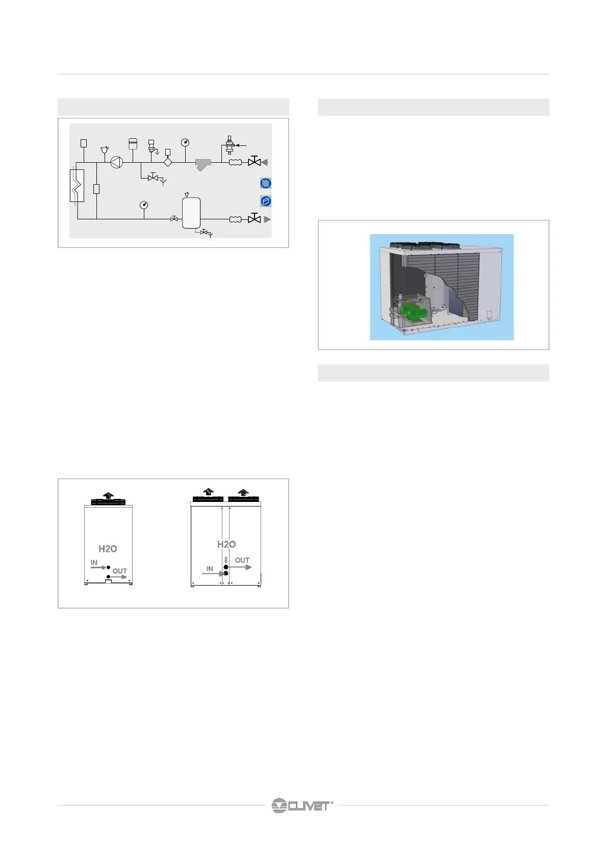
The unit is equipped with outlets for the pump emptying and
storage.
Outlets are accessible from the rear side (left side in the fig-
ure).
Storage content :
size 82¸122 80 litres
size 162¸302 130litres (optional)
4.8 WATER CIRCUIT EMPTYING
4.9 RECOVERY EXCHANGER
1. Charged system pressure
switch
2. vent
3. pump
4. expansion tank
5. safety valve
6. flow switch
7. pressure switch/thermometer
8. filter
9. filling valve
10. antivibration joints
11. user side exchanger
12. Differential pressure switch
13. Discharge cock
14. inertial storage tank
STANDARD HYDRAULIC CIRCUIT
• water side safety valve
• impurity trap with filter
• centrifugal pump
• antifreeze heater protection to pumping station
• drain valve
OPTIONAL - The unit can be equipped with exchangers to
recover the partial condensation heat.
The customer is responsible for the management of the
circulation pump, valves, thermostats, etc
The recovery input water must not be below 25°C, in the
event that, wrongful operations and breakages of the unit can
occur .
Water connections must be performed carefully as for the
evaporator (filter, circuit washing, etc) .
Perform all necessary interventions to avoid the RISK OF
FREEZING (tubes insulation, emptying of circuit, addition of
glycol, anti-freeze heaters) .
Water temperature can reach high temperatures (up to 100°
C), therefore:
• avoid the RISK OF BURNS by adopting the necessary
precautions (insulation of tubes, temperature detecting
station on water if the sanitary use is foreseen, etc)
• Install safety valves and specifically dimensioned
expansion tanks in the hydraulic circuit.
 Loading...