10 MODULAR CONFIGURATION UNITS
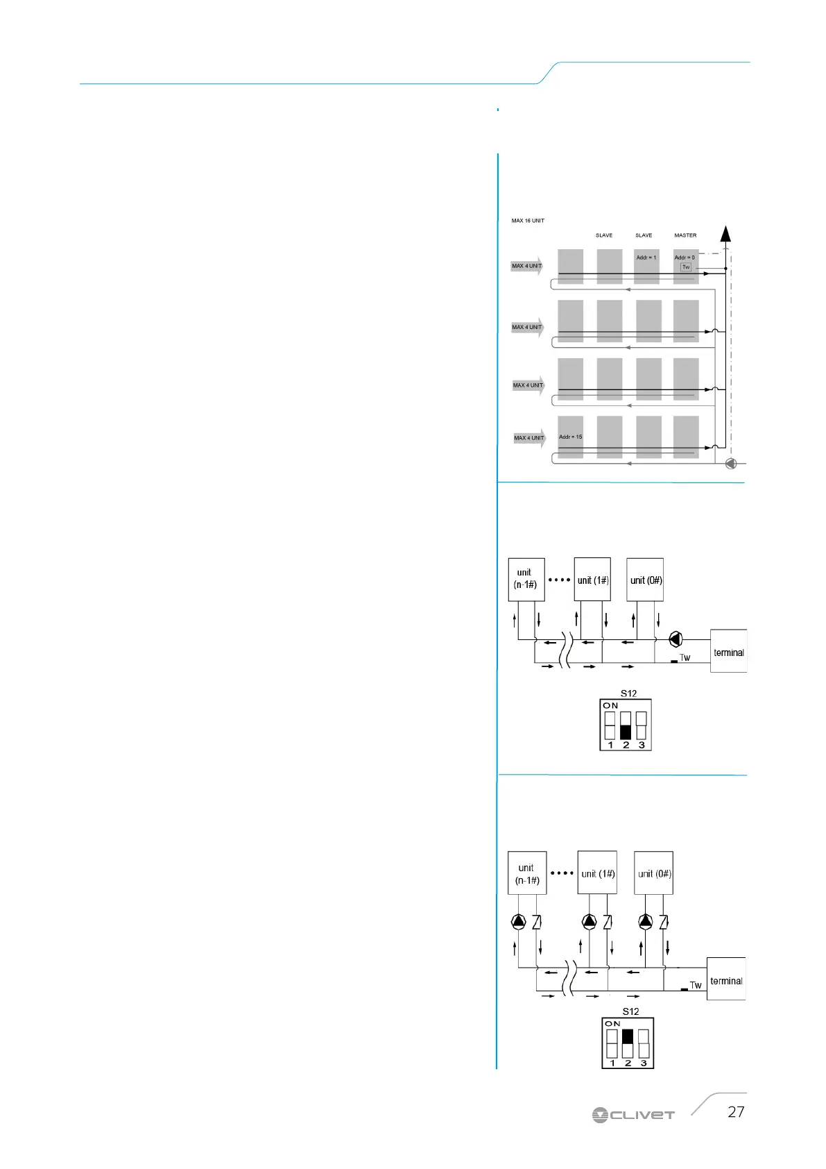
System diagram with inverted return
connection
Modular configuration units
Maximum 16 total units.
Maximum 4 units in the same water branch.
The modular system is controlled by the MASTER unit
(address=0), → Electrical connections
All units must be electrically connected to each other with 3-
conductor shielded cable →
Electrical connections
Each module can be equipped with inertial system storage
tank
Is possible to have a hydronic assembly installed on board.
It is possible to provide an external pumping unit, sized for
the entire capacity of the modular system (responsibility of
the Customer). The pumping unit will be managed by the
Master unit through a potential-free contact and 0-10V signal
→
electrical connections
Single/multiple pump system
Set up the DIP S12-2 according to the type of system.
Single water pump
The retaining valve is not necessary with this configuration.
The pump control is only activated on the master unit
Multiple water pumps.
A retaining valve for each unit is necessary with this
configuration.
Pump control is activated on each unit.
TW probe - Total water
It must be installed on the supply of the unit, as far away as
possible.
SINGLE UNIT: antifreeze function
MODULAR UNIT: thermoregulation (see diagram below)
Single water pumps.
dip S12-2 = OFF
Multiple water pumps.
dip S12-2 = ON
 Loading...