M03Q40G6-03 30/07/08 pag 13
POSITIONING
GENERAL
For installing air-conditioning systems, it is necessary to
consider the following:
• the technical spaces necessary for the machine and
system
• the place where the machine will be installed
• the transport of thermal carrier fluids and relevant
connections to the unit:
o water
o air
o refrigerant (unit in more sections)
• electrical connections
If these aspects are not evaluated carefully, they can affect
the performances and the working life of the unit.
FUNCTIONAL CLEARANCES
When placing the unit, please respect the functional
clearances indicated in DIMENSIONS section.
The functional spaces need to be observed because of the
following:
• to guarantee the good operation of the unit
• to allow the performance of all maintenance operations
• to protect the authorized operators and exposed
people
If more units are placed close to one another, the functional
spaces must be doubled.
POSITIONING
1. The units are designed for INDOOR installations,
performed in fixed positions and in areas accessible
only to qualified and authorized personnel
2. SAFETY VALVE (only if present on the unit) : the
installer is responsible for evaluating the opportunity
of installing drain tubes, in conformity with the local
regulations in force ( EN 378 )
3. Install the unit raised from the ground
4. avoid installations in places subject to flooding
5. Verify that the fixing/supporting points are level and
suitable to support the weight of the unit (see the
weight and the weights distribution)
6. It is recommended to put the unit on specific
antivibration devices
Each support point of the unit sustains a different
weight. Therefore, each anti-vibration device is sized
for a specific support point, and can only be placed
there. The anti-vibration devices must therefore be
placed in accordance with the instructions provided
with them and with the dimensional drawings in which
the support points are indicated by W1 , W2 , W3 etc .
On each anti-vibration device (if provided by CLIVET),
its identifying code is stamped, for example C6100100
Flexible joints are necessary on all the hydraulic/
aeraulic connections (the joints are not supplied by
Clivet)
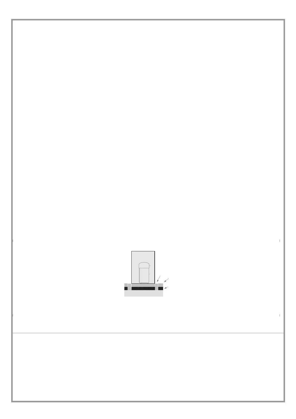
1
3
2
1. elastic joint
2. floating floor
3. soundproofing
Prevent the transmission of vibrations.

 Loading...