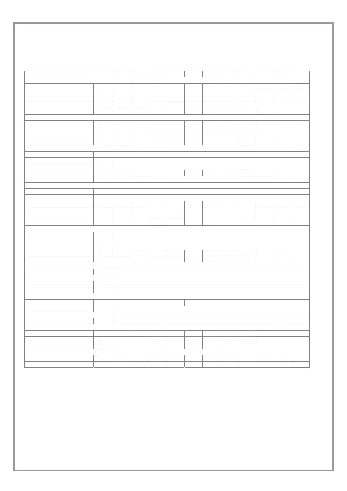
TECHNICAL DATA
Application: Terminal units
SIZE 17 21 31 41 51 61 71 81 91 101 121
Cooling
Cooling capacity 1 kW 5,95 6,42 7,9 10,5 13,4 16,7 20,2 22,1 25,8 30,5 35
Compressor power input 1 kW 1,51 1,64 1,95 2,4 3,15 3,78 4,82 5,02 5,88 6,56 7,55
Total power input 2 kW 1,52 1,65 1,96 2,41 3,16 3,79 4,83 5,03 5,89 6,57 7,56
EER 3,91 3,89 4,03 4,36 4,24 4,41 4,18 4,39 4,38 4,64 4,63
ESEER 4,29 4,25 4,54 4,84 4,48 4,7 4,59 4,92 4,86 5,13 5,04
Heating
Heat output 3 kW 7 7,63 9,28 12 15,6 19,1 23,4 25,1 29,5 34,3 39,3
Compressor power input 3 kW 1,89 2,06 2,53 3,02 4,12 4,62 5,9 6,39 7,21 8,17 9,22
Total power input 2 kW 1,9 2,07 2,54 3,03 4,13 4,63 5,91 6,4 7,22 8,18 9,23
COP 3,68 3,69 3,65 3,96 3,78 4,13 3,96 3,92 4,09 4,19 4,26
Compressor
Type of compressors SCROLL
No. of Compressors 1
Std Capacity control steps 1
Refrigerant charge (C1) kg 0,8 0,8 0,9 1,1 1,6 1,7 2,4 2,7 3 3,3 3,6
Refrigerant circuits 1
Internal exchanger
Type of internal exchanger 4 PHE
No. of internal exchangers Nr 1
Water flow rate 1 l/s 0,28 0,31 0,38 0,5 0,64 0,8 0,97 1,06 1,23 1,46 1,67
Useful pump discharge
head
1 kPa
56 54,1 53,3 43,4 37,8 59,6 55,1 49,5 43,8 143,5 112,1
Water content l 0,6 0,6 0,8 0,8 0,9 1,1 2,2 2,5 2,9 2,9 3,2
Exsternal exchanger
type of external exchanger 4 PHE
No. of exsternal
exchangers
1
Water flow rate 1 l/s 0,36 0,39 0,47 0,62 0,79 0,98 1,2 1,3 1,51 1,77 2,03
pressure drop kPa 15 17 16 24 28 29 33 29,5 29,7 39,3 42,5
Connections
Water fittings 5 1"GAS F
Hydraulic circuit
Max water side pressure kPa 550
Safety valve calibration kPa 600
Exspansion vessel
Expansion vessel capacity l 1 2
No. of expansion vessels 1
Powee supply
Standard power supply 230/1/50 400/3/50+N
Dimensios
Length mm 402 402 402 402 402 573 573 573 573 573 573
Depth mm 602 602 602 602 602 604 604 604 604 604 604
Height mm 785 785 785 785 785 858 858 858 858 858 858
Standard unit weights
Shipping weight kg 78 79 83 85 99 111 125 140 153 155 160
Operating weight kg 80 81 85 88 102 114 128 143 157 159 164
(1) data referred to the following conditions :
internal exchanger water = 12/7°C
external exchanger water = 30/35°C
(2) The total absorbed power is obtained adding the compressors absorbed power + the power absorbed by the auxiliary
circuit.
(3) data referred to the following conditions :
WATER TO INTERNAL EXCHANGER 40/45°C
External exchanger inlet water = 10°C
The water flow in the external exchanger is the same of the cooling operation.
(4) PHE = plates
(5) water connections both source side and utility side
 Loading...