M03Q40G6-03 30/07/08 pag 19
CONNECTION TO THE MAINS
1. Make sure that the sectioning device at the beginning of
the unit’s power line is opened, locked and equipped
with a signal.
2. Open the general line disconnecting switch (if present)
3. Verify that the net is in conformity with the data shown
in the registration plate placed on the electrical board.
4. Check the dimensional drawing for the input of the
electrical lines
5. Take away the closing plate placed on the electric
board (ONLY IF PRESENT) and drill a hole through it
to pass the cables through)
6. Protect the cables, using the fairlead of an adequate
size.
7. Using the layout of the electrical diagram, single out the
connecting terminals of the electrical supply cables, of
the neutral (if foreseen) and the PE protection cable
8. Connect the cables to the relevant terminal boards
9. Before supplying power to the unit, make sure that all
the safety devices that were removed during electrical
connections are positioned again.
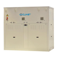
SYSTEM COMPOSITION
The system is composed of the following modules; some are optional that could be not installed.
Some are supplied in packages separate from the unit: check the shipping document descriptions.
Test
Comfort
ECO
ELFOENERGY
!
!
!
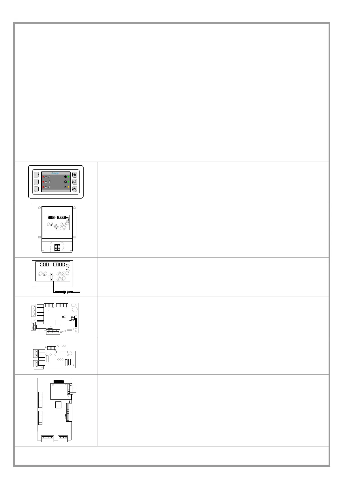
USER AMBIENT TERMINAL
Permits setting the unit function modes (cooling – heating, ECO) and to display the alarms
(ELECTRIC, REFRIGERATOR, WATER).
This is standard on certain types of unit
LN9192
S
T
A
T
U
S
S
E
T
A
L
A
R
M
2
1
REMOTE KEYPAD
OPTIONAL
The interface terminal enables to control every machine function, to program the different
adjustment parameters and possibly to display the unit statuses and alarms.
It remotely repeats all functions available on the machine keyboard
SERVICE KEYPAD
OPTIONAL
Useful during the maintenance operations; it is fitted with a cable with automotive rapid connector
for the utilisation in proximity to the unit.
The functionalities are analogous to the remote keypad ones.
MAIN ADJUSTMENT MODULE
It controls unit (inlets, outlets, configuration parameters)
EXPANSION PLUG-IN MODULE
It is connected to the main module by a coupling comb.
This may be fitted on the unit depending on the unit type and the accessories that are installed.
81234567
CN2
1210911
16
+5V
13 14 1 5
gnd
1917 18 2120
SERIALE
TTL / RS485
CN1
gnd
12VAC
+-
SERIAL CONVERTER TTL/RS485
OPTIONAL
Plugged-in in the main module on the electric board (see lay in the wiring diagram). It is possible
to connect up to 127 units with a single supervision system.
The connection with a PC must use a RS485/232 converter; the serial line RS232 can be max. 10-
m long.
CONNECTIONS:
make reference to the electrical panel and to the SIGNALS AND DATA LINES paragraph
 Loading...