M03Q40G6-03 30/07/08 pag 15
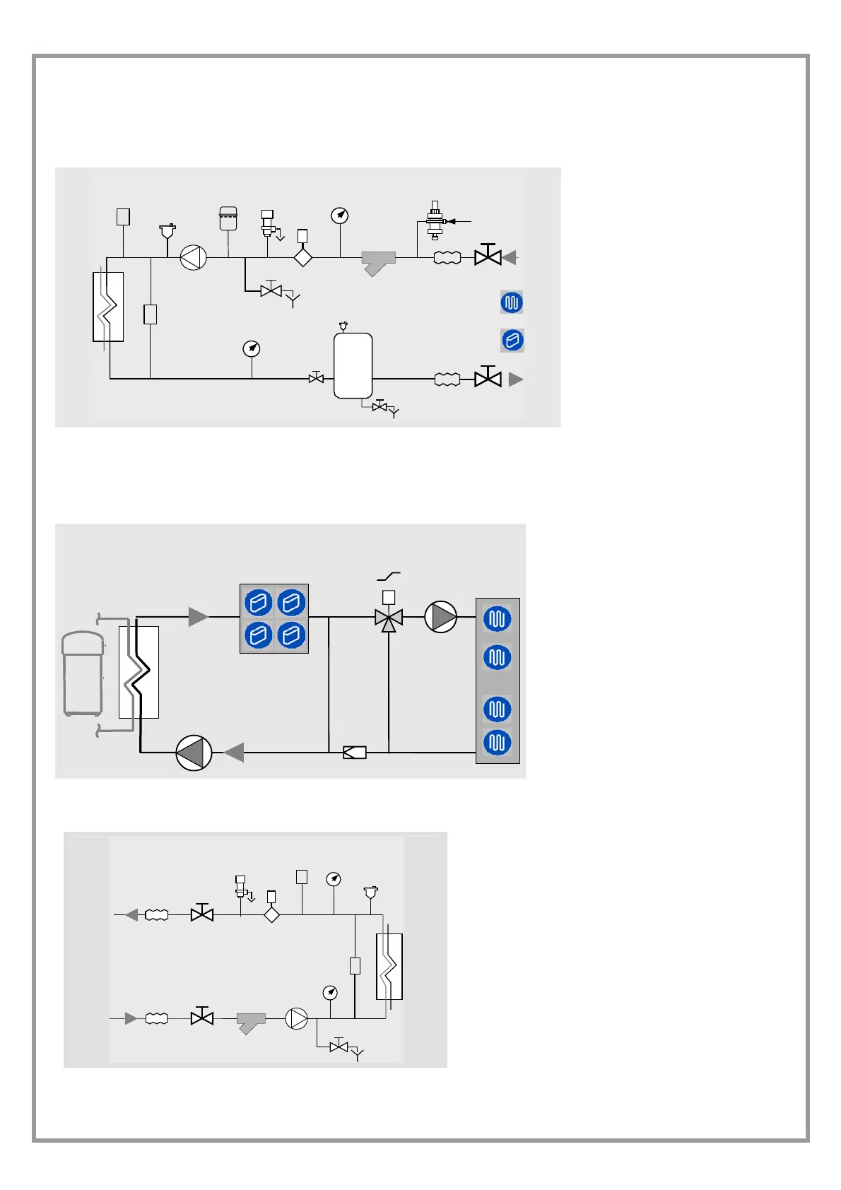
DIAGRAM OF RECOMMENDED USE SIDE CONNECTION
Depending on the type of machine and the selected setup, some components may be integrated into the unit.
P
9
11
14
8
F
2
3
5
12
7
6
4
8
1
10
13
P
7
1. Charged system pressure switch
2. vent
3. pump
4. expansion tank
5. safety valve
6. flow switch
7. pressure switch / thermometer
8. filter
9. filling valve
10. antivibration joints
11. user side exchanger
12. Differential pressure switch
13. Discharge cock
14. inertial storage tank
The accumulation tank is necessary in the event of the following:
• the water in the system is very low
• the unit will not be used in a private house (in an industrial process or other)
USE SCHEMA
8
1
2
3
4
5
1. fancoil
2. 3-ways radiant panels
3. radiant pump
4. radiants
5. pump
for more details see the ELECTRICAL DATA
section
RECOMMENDED SOURCE SIDE CONNECTION SCHEMA
P
8
F
2
3
56
1
P
4
7
8
9
10
1. Antivibration joints
2. Shut-off valve
3. Safety valve
4. Flow switch
5. System min. pressure manostat
6. Pressure switch / thermometer
7. vent
8. Differential pressure switch
9. Pump
10. Filter
 Loading...