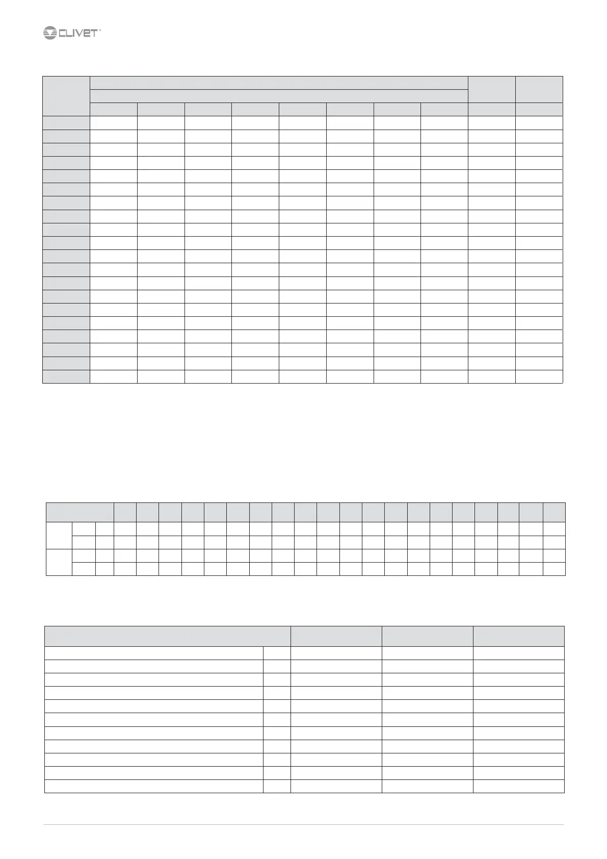
Sound levels
Size
Sound power level (dB)
Sound
power level
Sound
pressure level
Octave band (Hz)
63 125 250 500 1000 2000 4000 8000 dB(A) dB(A)
10.2 78 70 62 52 52 43 41 40 60 44
12.2 78 69 62 56 52 44 43 38 60 44
14.2 78 67 61 57 54 46 44 39 60 45
16.2 78 71 66 63 53 49 46 41 64 49
19.2 78 73 67 63 55 51 47 42 65 49
22.2 78 73 65 62 55 52 47 42 64 49
27.2 78 73 66 62 56 54 48 44 64 49
30.2 78 74 63 60 56 54 48 44 64 49
35.2 81 83 80 67 61 61 52 45 74 58
40.2 81 79 80 67 65 63 55 50 74 58
43.2 81 83 83 69 66 65
56 49 77 60
45.2 81 78 80 69 66 62 55 48 74 58
50.2 81 83 83 70 67 64 56 47 77 60
55.2 81 80 83 70 68 65 57 50 77 60
60.2 81 80 83 71 69 65 57 50 77 61
70.2 82 80 85 73 72 68 60 51 79 63
80.2 82 80 85 73 74 70 61 52 80 63
90.2 83 81 86 74 75 71 62 53 81 64
100.2 83 81 86 74 75 71 62 53 81 64
120.2 84 82 87 75 76 72 63 54 82 65
Sound levels refer to units with full load under nominal test conditions.
The sound pressure level refers to a distance of 1 meter from the outer surface of the unit operating in open eld.
Noise levels are determined using the tensiometric method (UNI EN ISO 9614-2)
Data referred to the following conditions:
Entering / leaving exchanger water temperature user side 12/7°C
Entering / leaving exchanger water temperature source side 30/35°C
Admissible water ow rates
Min. (Qmin) and max. (Qmax) water ow-rates admissibles for the correct unit operation.
10.2 12.2 14.2 16.2 19.2 22.2 27.2 30.2 35.2 40.2 43.2 45.2 50.2 55.2 60.2 70.2 80.2 90.2 100.2 120.2
Heating
side
Qmin [l/s] 0,8 0,8 0,8 1,0 1,1 1,1 1,8 1,8 1,8 2,4 2,4 2,4 2,9 2,9 2,9 3,8 3,8 5,3 9,5 10,5
Qmax [l/s] 4,2 4,2 4,3 4,8 4,9 5,1 8,8 8,8 9,3 11,4 11,9 12,2 14,4 15,0 15,4 18,3 19,0 23,5 28,0 29,0
Cooling
side
Qmin [l/s] 0,8 0,8 0,8 1,0 1,1 1,1 1,9 1,9 2,6 2,6 2,6 3,5 3,5 3,5 4,5 4,5 5,0 5,0 8,5 8,5
Qmax [l/s] 3,5 3,5 4,3 4,4 4,9 5,1 8,5 8,5 11,5 11,5 11,5 14,5 14,5 15,0 18,0 18,5 21,5 22,0 27,0 27,0
Overload and control device calibrations
Intervention Reset Value
High pressure switch (gas side) [kPa] 4050 3300 –
Low pressure alarm (gas side) [kPa] 450 600 –
Low pressure switch (GEO) (gas side) [bar] 200 350 –
Antifreeze protection [°C] 4 6,0 –
high pressure safety valve (gas side) [kPa] – – 4500
Low pressure safety valve (gas side) [kPa] – – 3000
Max no. of compressor starts per hour (gas side) [No] – – 10
Dierential pressure switch (water side) [kPa] 3 5 -
Max. pressure without hydronic assembly (water side) [kPa] - - 1000
Max. pressure with hydronic assembly (water side) [kPa] - - 600
Safety valve calibration (water side) (1) [kPa] - - 600
(1) Available only with hydronic assembly option