9
Edition 2.0 2010/06
B. Use MC (Multi-contact) connectors for PV array terminals.
C. Connect the positive and negative terminals from the PV panel to positive (+)
terminals and negative (-) terminals on the PV-Inverter. Each DC terminal on Inverter
can withstand 20ADC.
D. Before connecting PV panels to DC terminals, please make sure the polarity is
correct. Incorrect polarity connection could permanently damage the unit. Check
short-circuit current of the PV string. The total short-circuit current of the PV string
should be less than the inverter’s maximum DC current.
E. High voltages exist when the PV panel is exposed to the sun. To reduce risk of
electric shock, avoid touching live components and treat connection terminals
carefully.
5) Checking
A. When the PV panels are connected and their output voltage is greater than 100
VDC but the AC grid is not yet connected, the message on the LCD display produce
the following messages in order: “MODEL= XkW”-> “Waiting” -> “Disconnect Grid”.
The display repeats “Disconnect Grid” and the RED “fault LED” turns on.
B. Close the AC breaker or fuse between PV-Inverter and grid. The normal
operating sequence begins.
C. Under normal operating conditions the LCD displays “Pac =xxxx.xW”. That is the
power fed to the grid. The green LED turns lights-up.
D. This completes the check.
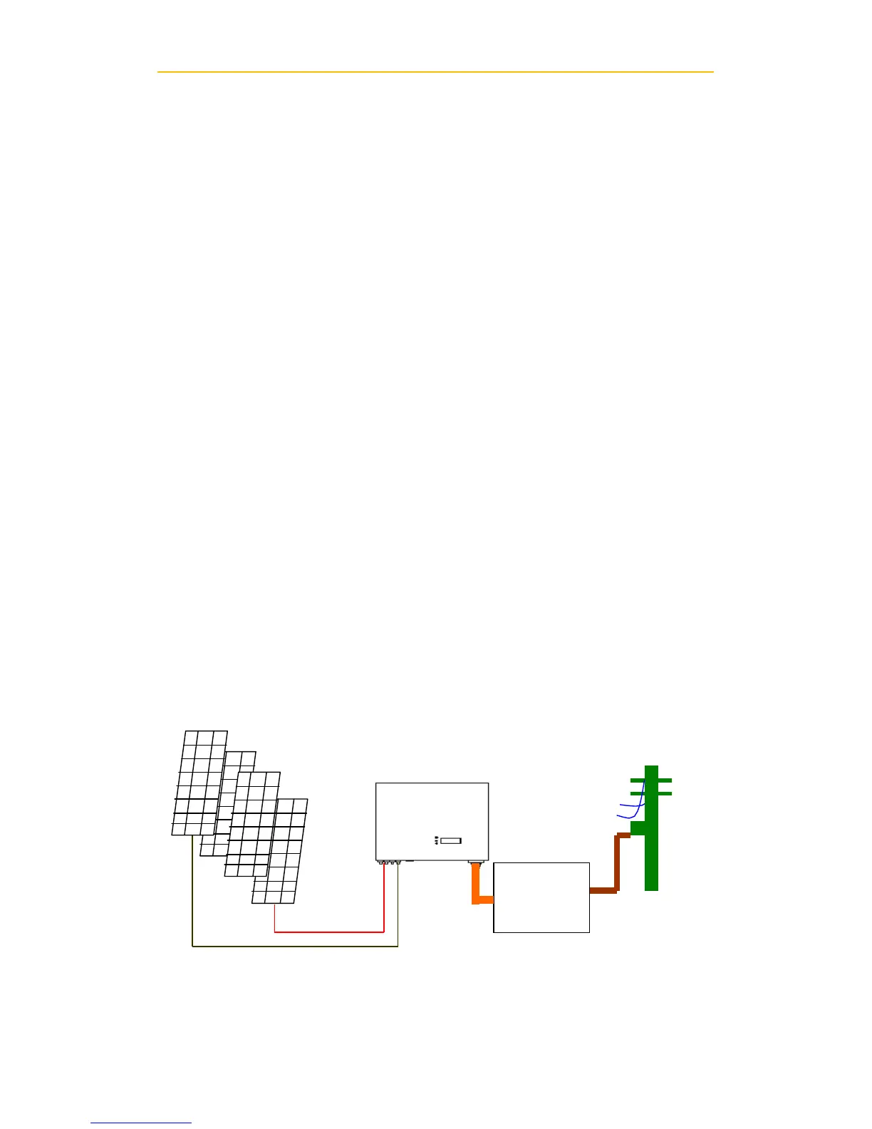
6) System Diagram
A. PV Panel: Provide DC power to inverter
B. CMS: Converts DC (Direct Current) power from PV panel(s) to AC (Alternating