6.2.2 PORTA Analog Control Selection
The ANSEL0 register is used to configure the input mode of I/O pin to analog mode. Setting the
appropriate bit in ANSEL0 to 1 will cause all digital read operations of the corresponding pin to return to 0
and make the analog function of the pin work normally. The state of the ANSEL0 bit has no effect on the
digital output function. The pin with TRIS cleared and ANSEL0 set to 1 will still be used as a digital output,
but the input mode will become an analog mode. This can cause unpredictable results when performing
read-modify-write operations on the affected port.
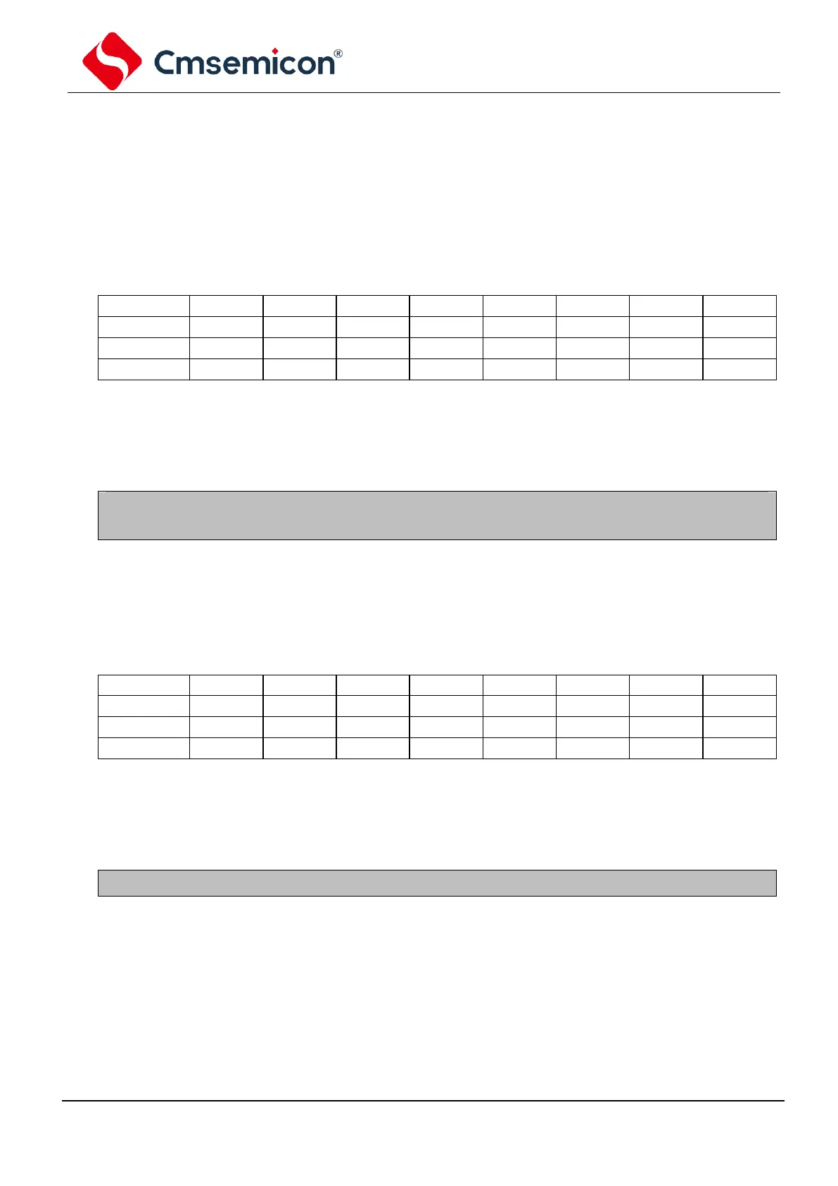
PORT A analog selection register ANSEL0 (110H)
Analog selection bit, select the digital or analog function of pin AN<7:0>
Analog input. The pin is selected as analog input.
Digital I/O. The pin is selected as port or special function
Note: ANS and ports are not corresponding, please check the pin diagram for specific corresponding
relationship.
6.2.3 PORTA Pull Up Resistance
Each PORTA pin has an internal weak pull up that can be individually configured. The control bits
WPUA<7:0> enable or disable each weak pull up.
PORTA pull up resistance register WPUA (07H)
Weak pull up register bit
Note: If pin is configured as output, weak pull up will be automatically disabled.