EasyManua.ls Logo

Cmsemicon SC8F577 Series - Pin Configuration

Default Icon
181 pages
Print Icon
To Next Page IconTo Next Page
To Previous Page IconTo Previous Page
Loading...
V1.8
SC8F577x
83 / 181
www.mcu.com.cn
11. PWM Mod
A programmable PWM module with 10-bit width in chip, which can be configured as 4 channels of
common period, independent duty cycle output and 1 channel of independent output, or 2 pairs of
complementary outputs and 1 channel of independent output.
The PWM output can be selected as RA1-RA5 or RA5-RA7RB5RB4 or RB0-RB4 through config.
Among them, PWM0/PWM1 and PWM2/PWM3 can be configured as complementary outputs.
11.1 Pin configuration
The corresponding PWM pin should be configured as output by setting the corresponding TRIS control
bit to 0.
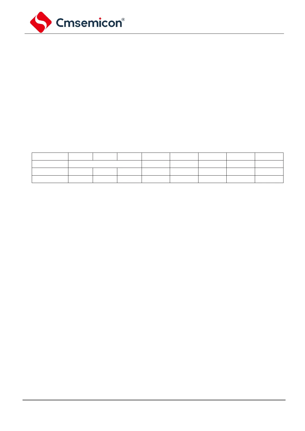
11.2 PWM Related Register
PWM control register PWMCON0 (13H)
13H
Bit7
Bit6
Bit5
Bit4
Bit3
Bit2
Bit1
Bit0
PWMCON0
CLKDIV[2:0]
PWM4EN
PWM3EN
PWM2EN
PWM1EN
PWM0EN
R/W
R/W
R/W
R/W
R/W
R/W
R/W
R/W
R/W
Reset value
0
0
0
0
0
0
0
0
Bit7~5
CYC2EN:
PWM clock division.
111=
Fosc/128
110=
Fosc/64
101=
Fosc/32
100=
Fosc/16
011=
Fosc/8
010=
Fosc/4
001=
Fosc/2
000=
Fosc/1
Bit4~Bit0
PWMxEN:
PWMx enable bit.
1=
Enable PWMx
0=
Disable PWMx

Related product manuals