11.7 Programmable dead-time delay mode
Complementary output mode can be enabled by configured PWMxDT_EN, and the dead-time delay
function is enabled automatically after enable complementary output mode.
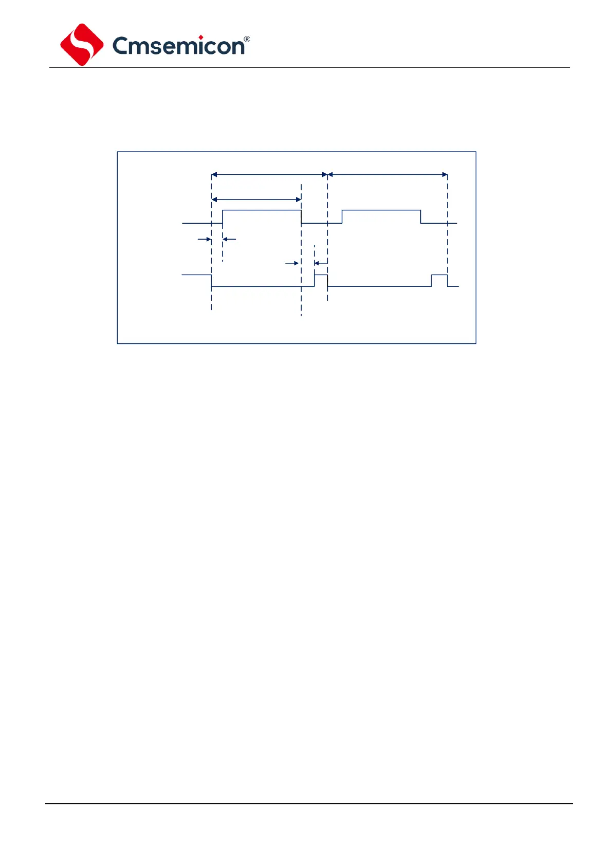
Fig 11-1: Sample of PWM dead-time delay output
Dead-time calculation formula:
td=(
PWMxxDT
[5:0]+1)*T
OSC
*
(
DT_DIV prescaler value
)
11.8 Configurate PWM
The following steps should be performed when configuring PWM mod:
1. Configure the PWMIOSx register to select the PWM output IO port.
2. Disable the output driver of PWM pin by setting the corresponding TRIS bit to 1 to make it an input
pin.
3. Set the PWM period by loading the PWMTH and PWMTL register.
4. Set the PWM duty cycle by loading the PWMDxL register and PWMDxxH register.
5. Set the PWM dead-time by setting the PWMCON1[6:5] and loading PWMxxDT register if
complementary output mode is required.
6. Clear the PWMIF flag bit.
7. Enable corresponding output by setting the PWMCN0[4:0].
8. After the new PWM period starts, enable PWM output:
- Wait for PWMIF set to 1.
- Enable the PWM pin output driver by clearing the corresponding TRIS bit.