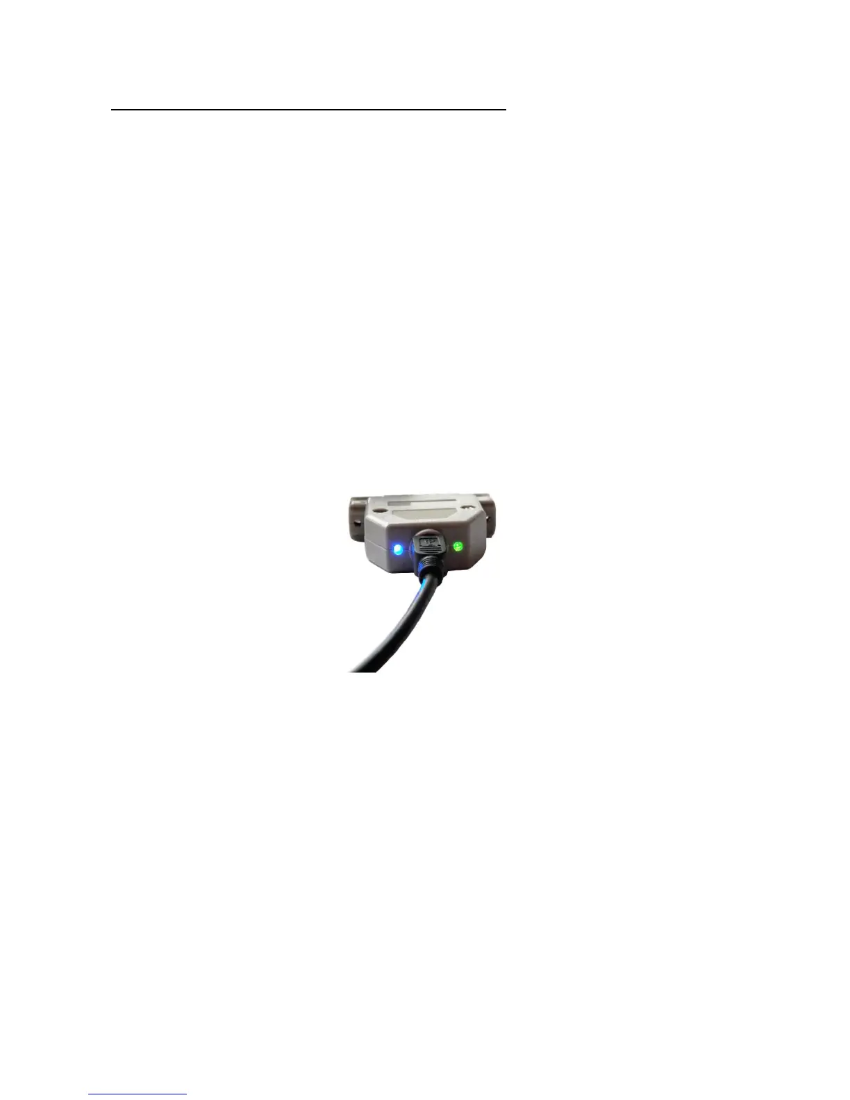
4. LED feedback signals on the UC100 controller
There are 2 LEDs located and floating out of the UC100 DSUB backshell.
These LEDs providing informations about the UC100 working states and these states are
the following:
- The green (power LED) lighting continiously indicates normal operation and that the
UC100 is up and running normally.
- The green (power LED) blinking with about 5Hz frequency indicates a firmware error.
- The green (power LED) blinking slow, with about 1Hz indicates a firmware update in
progress and in this case wait till the firmware update procedure ends and the green LED
returns to a continuous lighting state.
- The blue (communication LED) if on indicates that the connection between Mach3 and
the UC100 controller is active. The LED sometimes blinks (mostly on slower computers)
and sometimes lights continiously (mostly on fast computers).
The 2 LEDs on the backshell of the UC100 controller.