C32 (Rev. 5) User Manual
___________________________________________________________________________
User’s Manual Page 11
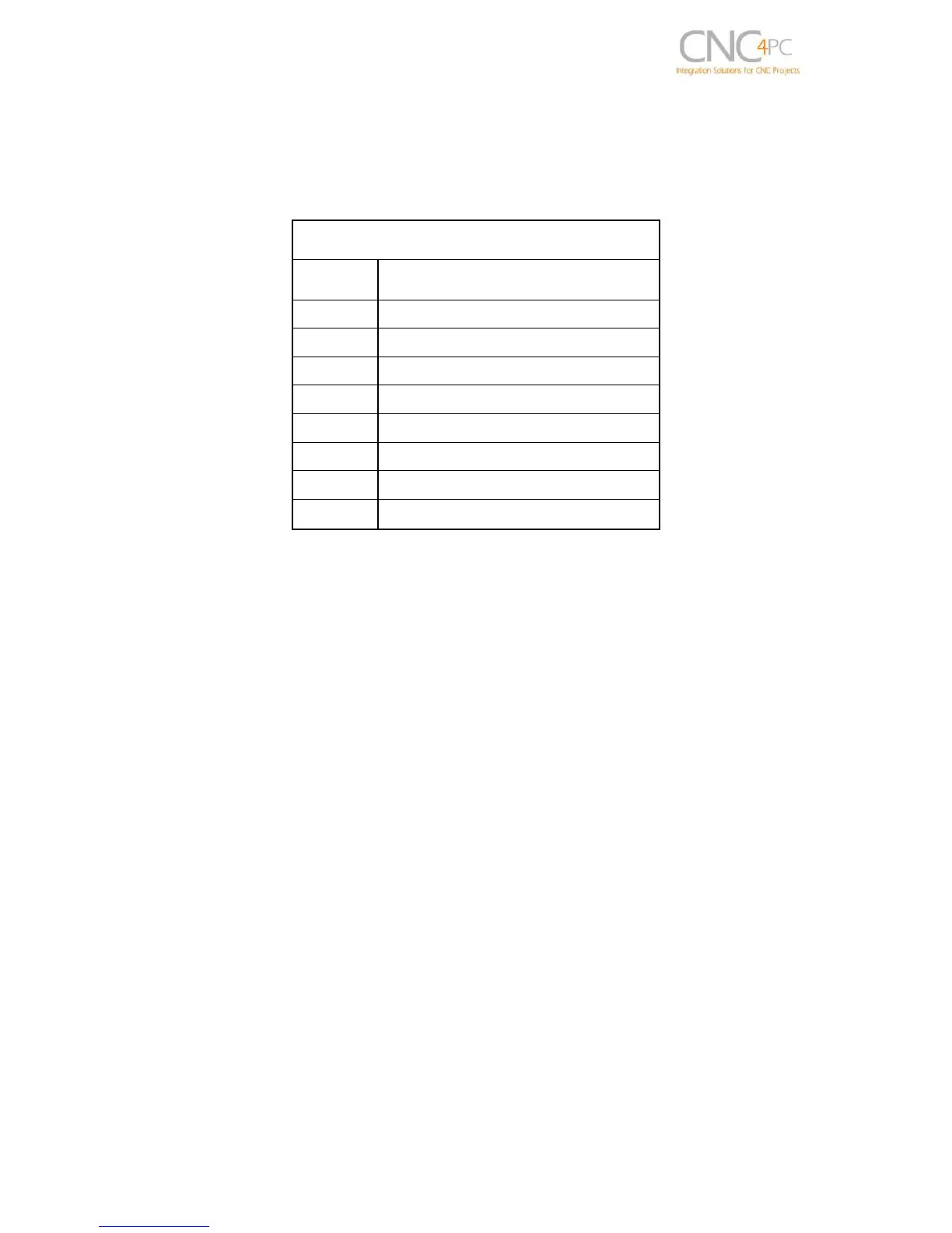
RJ45 for VFD Connection
This RJ45 port let you make an easy connection between this board and the VFD.
REL 1 Normally Open Contact
REL 2 Normally Open Contact
An. GND: Ground of the Analog output signal
Analog Output: Isolated Analog Output Signal (0-10V)
VFD Alarm: Alarm signal generated by the VFD. (See VFD ALARM JUMPERS section)
Ext. 12VDC or 24VDC: External 12VDC or 24VDC power supply used to enable the
VFD.
Relay Common: The signal or voltage wired to this terminal can be connected to the
common terminals of the relay 1 and relay 2. Use the on-board RELAY COMMON
JUMPERS to do this connection. Remove the jumper if this connection is not required.