C32 (Rev. 5) User Manual
___________________________________________________________________________
User’s Manual Page 10
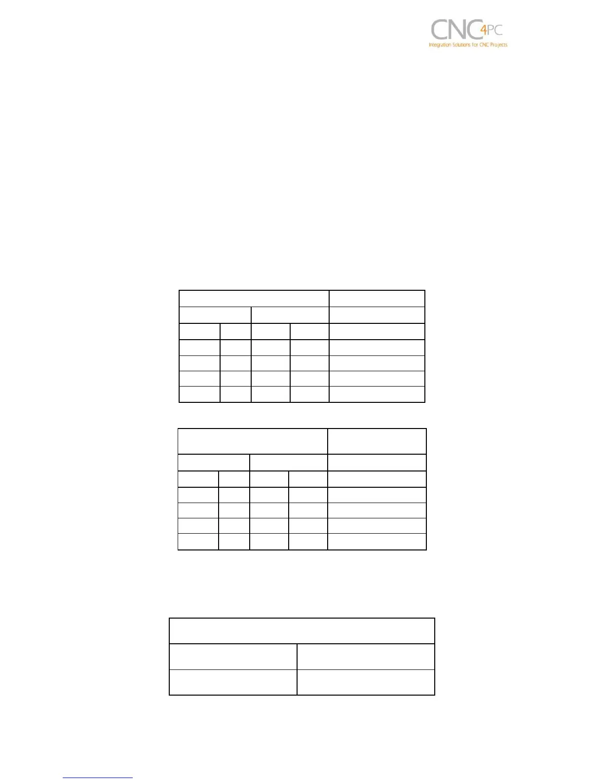
7.1 Operation Mode Selection Jumper
This jumper allows selecting the way how the relays are activated when a PWM signal
and REV signal are present in the pins 1_14 and 1_16.
In US mode one relay is used to start on CW and the other one to start on CCW. In
international mode one relay is used for on/off, and the other one to indicate the CW or
CCW rotation of the spindle motor. This board uses the step and direction setting for
the spindle motor under motor output in Mach3 to generate the required action on the
relays. For both cases the presence of PWM will indicate spindle start.
See the tables below.
Relay 1 and 2 (Pins 16 “Port 1”)
They can be used to control the VFD. The relay specifications are shown in the table
below.
ELECTROMECHANICAL RELAYS
SPECIFICATIONS