C32 (Rev. 5) User Manual
___________________________________________________________________________
User’s Manual Page 6
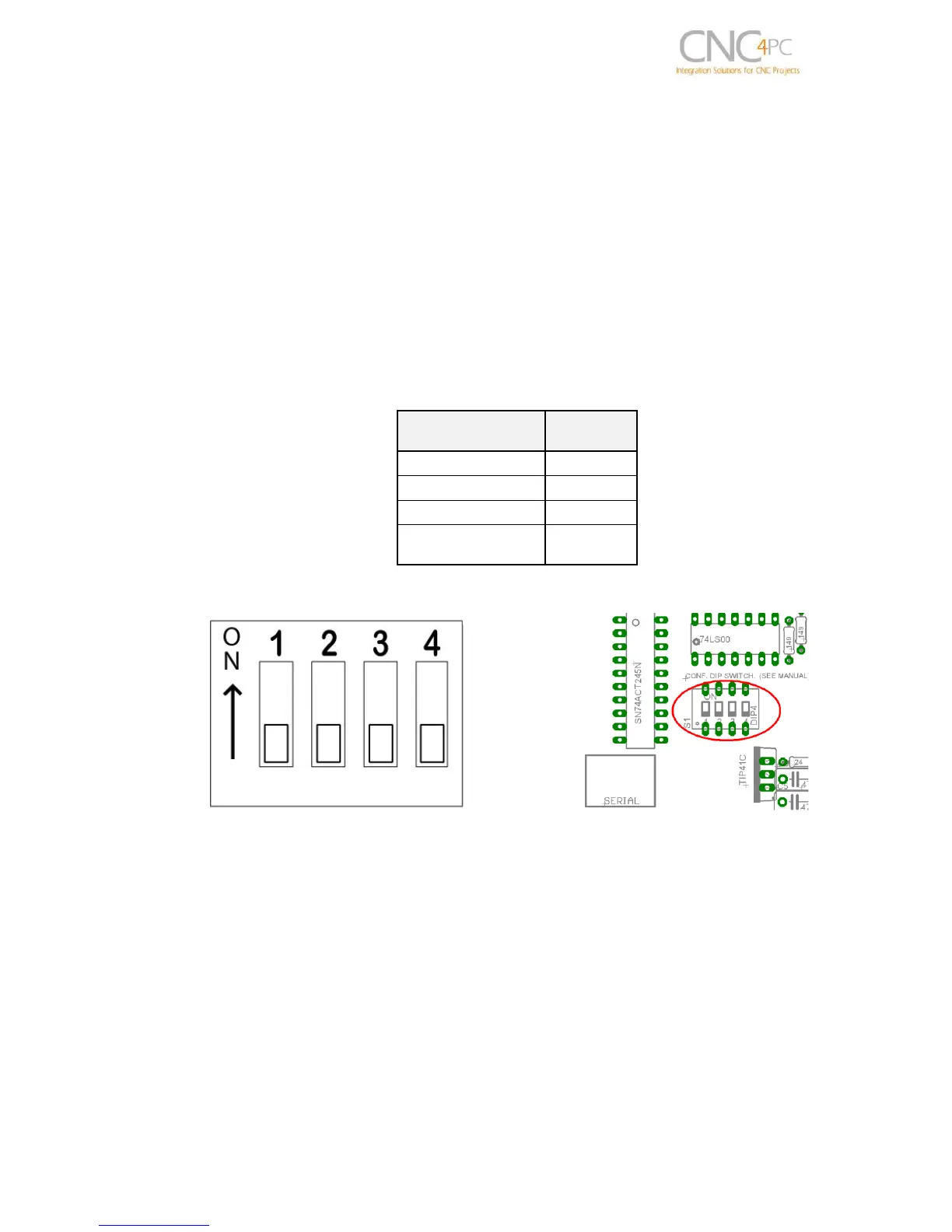
5.0 CONFIGURATION DIPSWITCH
DIPSWITCH allows activating or deactivating the SCHP detection function, and
selecting the driver to use and delays an enable signal for external devices.
5.1 Position 1
The enable output (Pin 17-Port 2) will be activated when the driver enable process
starts. A delay in the signal activation time could be added by selecting the OFF position
in the DIPSWITCH.
The table below shows the delay time for each supported driver.
SWITCH 1 OFF: Delayed enable output (Pin 17-Port 2).
SWITCH 1 ON: Non Delayed enable output (Pin 17-Port 2).
5.2 Position 2
Safety Charge Pump “SCHP”. (Pin 17 “Port 2”)
This board takes advantage of Mach ability to send a specific frequency through one of
the pins of the parallel port when the program is in control of the system.
Selecting the SCHP operation mode