C32 (Rev. 5) User Manual
___________________________________________________________________________
User’s Manual Page 20
Note: Pins (2_2 - 2_9) are configured as inputs and they are only accessible through
the DB25 for Pendant.
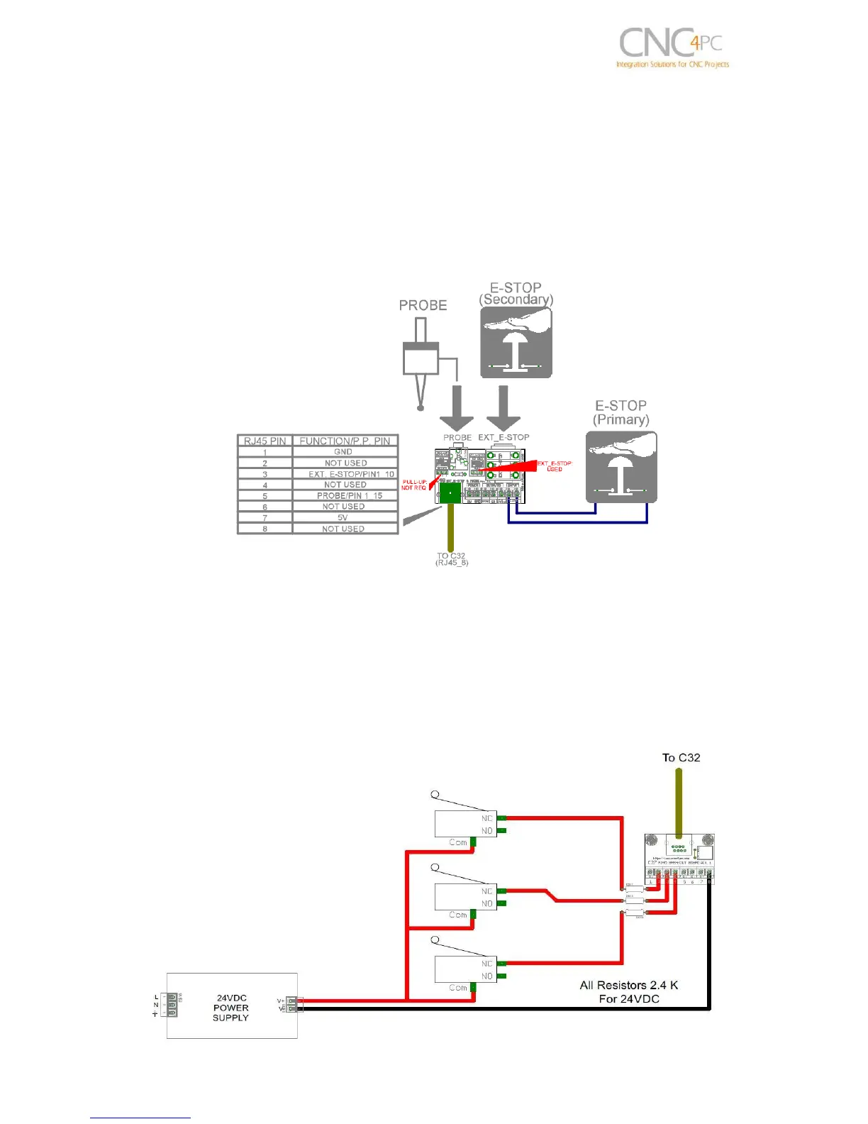
CONNECTING A C48
RJ45_8 provides an easy way to wire an External Probe and an external (Secondary)
E-Stop. Image below shows a wiring sample for this connection
Note: The primary E-stop can be connected to C32 E-Stop terminals or to the C48 E-Stop input
terminals.
11.0 WIRING DIAGRAMS
This connection is for signals of 24VDC, allows what inputs signals can be to 24V. This
requires limiting resistors.