6
ENGLISH
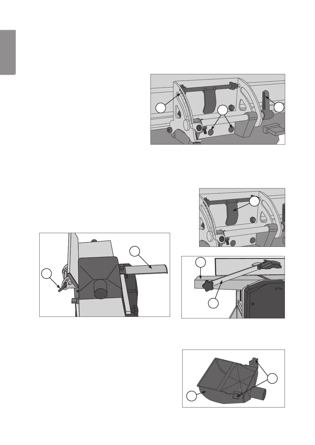
C
10A
10B
10R
10K
10B
10F
10G
10E
10H
6. Use
Warning! Alwayspull out electrical cable plugs from thesocket before servicing and adjusting theplane irons,
cutting depth and other settings.
6.1 Mounting the angle stop
1. Move theobject sideways:
- Fold down thelocking bridge (R) and move thestop
sideways.
- Securely lock thestop by pressing thelocking bridge
(R) upwards.
6.2 Mounting the extraction hood
Attention! Foryour safety theextraction hood must always be mounted when both level and surface planing;
and both locking levers (H) must be pressed in order for themotor tostart.
When planing, theextraction hood (E) must be mounted as it acts as acover!
4. Pull both locking levers (H) on theextraction hood (E).
5. Lay thehood (E) on thelevelling table so that thelocking
levers (H) fit thevents in thelevelling table (G); push in
thelocking levers.
1. Screw tight thestop on theside of
theoutflow table with two screws (A).
2. Set desired angle: Openthelocking
lever (B) and set desired angle on
theshell (C), tighten locking lever.
2. Open thelocking lever (B) and angle thestop slightly. 3. Loosen thearm (F) holding thecutter cover
(K) and unfold it; pull thecutter cover to
theside.