8
ENGLISH
7. Changing planing irons
1. Planing irons can be sharpened (HSS) up to three times (3×0.05 mm):
2. Remove theangle stop and lift up thearm holding thecover.
3. Turn thecutter by hand until one of theiron’s tightening screws is visibly turned upwards.
4. Loosen thefour screws on thesteel holder (which press theplaning iron against thecutter) with
theaccompanying Allenkeys.
5. Remove theplaning iron and steel holder out of theslot on thecutter. Withanoiled cloth, clean thesteel
holder, slot and planing iron, removing waste, shavings anddust.
6. Sharpen theplaning iron or change it. Puttheplaning iron and steel holder in theslot again and lock them in
place by turning thetightening screws clockwise (but do not tighten fully), make sure theplaning iron is lying
against thecutter allowing thetwo adjusting screws to fit into their notch in theplaning iron.
7. Adjust theedges sticking out with theaccompanying 4 mm Allen keys by turning thesteel holder’s
two adjusting screws in and out according to requirement. Aftersetting correctly, tighten thefastening
screwsagain.
8. Check how much cutter steel sticks out above theoutflow table with atemplate or ruler on theoutflow
table. Themaximum protrusion over theoutflow table is: 0.1 mm. (measure several times over thewidth of
thewhole planing blade).
9. Tighten thescrews and measure theedges sticking out again after tightening. Attention! Donot use akey
with alonger shaft than theone delivered.
10. Repeat theprocedure with theother planing iron, then check that both planing irons stick outthe
sameamount.
8. Raising and lowering planing table
Take out thecrank and mount it on theaxle on theabove side of theplane, turn thecrank until it goes down
and locks tightly on theaxle; remove after setting.
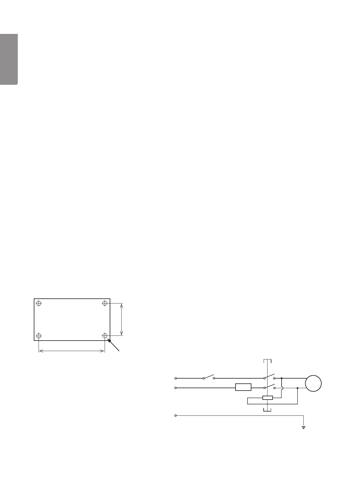
9. Mounting the planer/thickesser on a bench etc.
The level and surface plane should be mounted on astable bench, table etc. Theplane weighs 26 kg and
should be fastened to ahard, flat surface. Ithas four fastening holes (Ø 9 mm). Fastentheplanewith M8 bolts,
washers and locking bolts (not included).
240 mm
350 mm
4×Ø 9mm
10. Wiring diagram
M
Overload protection
230 V~
NVR switch