16 • Important: Always read and follow the operating instructions.
Performance, Custom
and Aluminum Wheels
Only tire technicians with experience and
training on custom wheels should attempt
to service expensive custom alloy or alu-
minum wheels and high-performance low-
profile tires.
Pre-Operation Notes:
• Ensure all weights have been removed.
• Clamp wheel from the outside.
• Use ample lubricant for mount and demounting.
• Always review wheel nicks and/or scratches
with the owner before servicing.
Performance Tires and Wheels •
Demounting
Follow these instructions for performance type tires
and wheels, including run-flat tires and their associated
wheels, and asymmetrical hump wheels.
1. Remove valve core and completely deflate tire.
2. Pull the bead loosener shoe away from the
machine and roll the tire into position against the
bumper pads. Position the tire with the valve stem in
the 2 o’clock position (in direct line with the bead
loosener shoe). Always loosen the bead on the nar-
row/mounting side of the wheel first (figures 2 and 28).
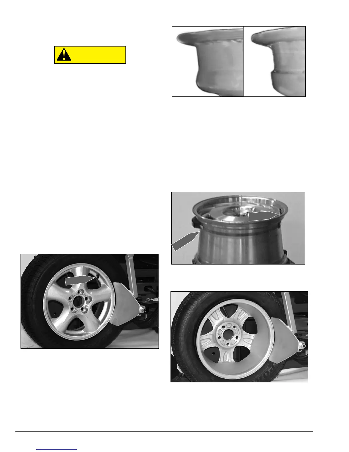
Figure 28 - Position Tire for Bead Loosening
AA. Wheels with an asymmetrical hump have a larger
“ledge” type hump around the wheel except at the
valve hole making them more difficult to mount and
demount (figure 29). Always loosen the beads near the
valve stem on both sides of rim.
Figure 29 - Asymmetrical Hump Wheel
AB. Some wheels/tires have a low pressure sen-
sor/transmitter strapped to the wheel (figure 30). This
is especially true on run-flat tire/wheel systems. The
sensor is positioned directly opposite from the valve
stem. Other low pressure warning systems have the
sensor as part of the valve. To avoid damaging the sen-
sor, always loosen the top bead with the valve stem at
the 2 o’clock position first, then loosen the bottom
bead with the valve stem at the 2 o’clock position, and
then continue to loosen the remaining circumference
of the beads as necessary. Avoid loosening at 180 deg.
(opposite) the valve.
Figure 30 - Wheel with Low Pressure Sensor/Transmitter
3. Loosen bottom bead, starting with valve stem at
2 o‘clock position next to the loosener shoe (figure 31).
Figure 31 - Loosen Bottom Bead