Document: 677-A0219_IM issue 1.4
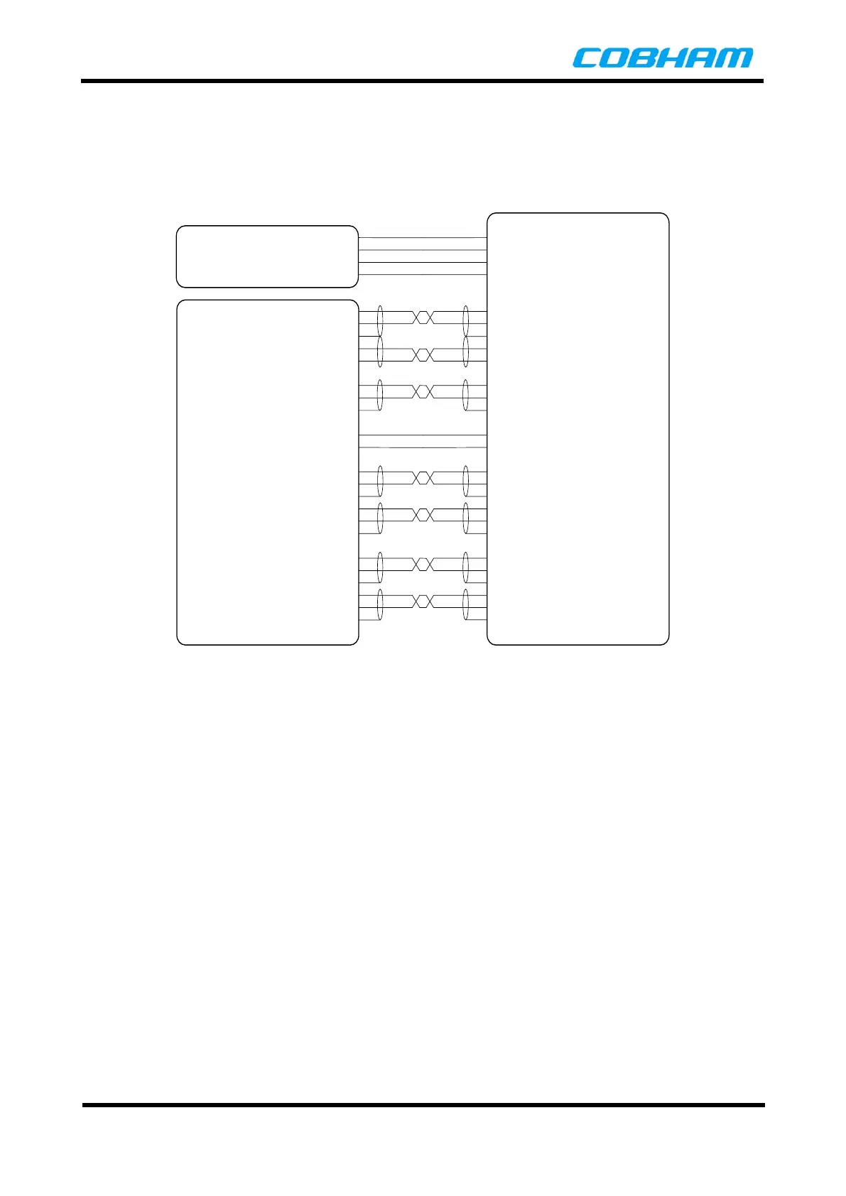
and the terminal connector. Multiple DC power pins are provided to reduce the series resistance of
the power cable bundle. If long power cable runs are required, a larger gauge wire will need to be
used over the length of the cable, and reduced to the appropriate gauge wire at the connector pin.
5. The Power Source for the UAV 200 Terminal should be 12VDC to 32VDC of at least 28W.
22 1
+VDC
+VDC
2
+VDC+VDC
18
GNDGND
19
GNDGND
8
24
RS232 Tx0
RS232 Rx0
9
GND
RS232 Rx
RS232 Tx
GND
7
25
RS232 CTS0
RS232 RTS0
RS232 RTS
RS232 CTS
10
27
RS232 Tx1
RS232 Rx1
26
GND
RS232 Rx
RS232 Tx
GND
11
RESETRESET
28
GNDGND
12
29
Ethernet Rx0+
Ethernet Rx0-
13
GND
Ethernet Tx0+
Ethernet Tx0-
GND
14
31
Ethernet Tx0+
Ethernet Tx0-
30
GND
Ethernet Rx0+
Ethernet Rx0-
GND
15
32
Ethernet Rx1+
Ethernet Rx1-
16
GND
Ethernet Tx1+
Ethernet Tx1-
GND
17
34
Ethernet Tx1+
Ethernet Tx1-
33
GND
Ethernet Rx1+
Ethernet Rx1-
GND
28
28
28
28
28
28
28
28
22
22
22
28
USER
EQUIPMENT
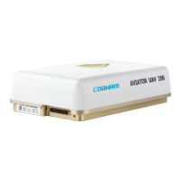
AVIATOR UAV 200
TERMINAL
Minimum
Wire Gauge
POWER
SOURCE
Figure 4-4: AVIATOR UAV 200 Wiring Diagram
4.5.6 Grounding
The AVIATOR UAV 200 terminal is grounded through the Alodined aluminium contact areas shown in Figure
4-5. The airframe attachment points should be free of paint and suitably protected against corrosion,
providing the ground path when the terminal is mounted. The resistance between the terminal base and the
airframe should be less than 5 mΩ.


 To Next Page